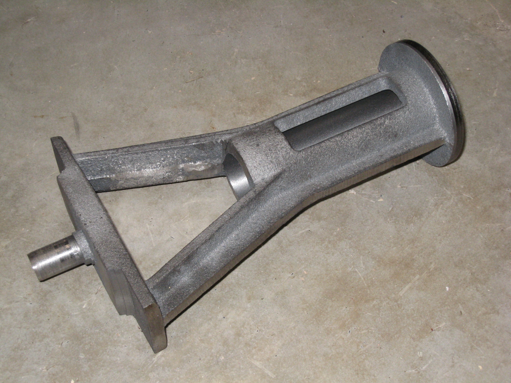
I decided to start with the machining of the Standard.
I planned the pattern to give a peg on the middle below the legs of the Standard.
This makes it much easier than chucking the top of the Standard and facing the leg so that they can be clamps to a face plate.
I also wanted to be able to turn the feet, bore the crosshead and face the top in essentially one setup.
My lathe is so short that the chuck, Standard and boring bar together are too long for the ways.
I also needed to make a steady rest to have a nice ridged setup.
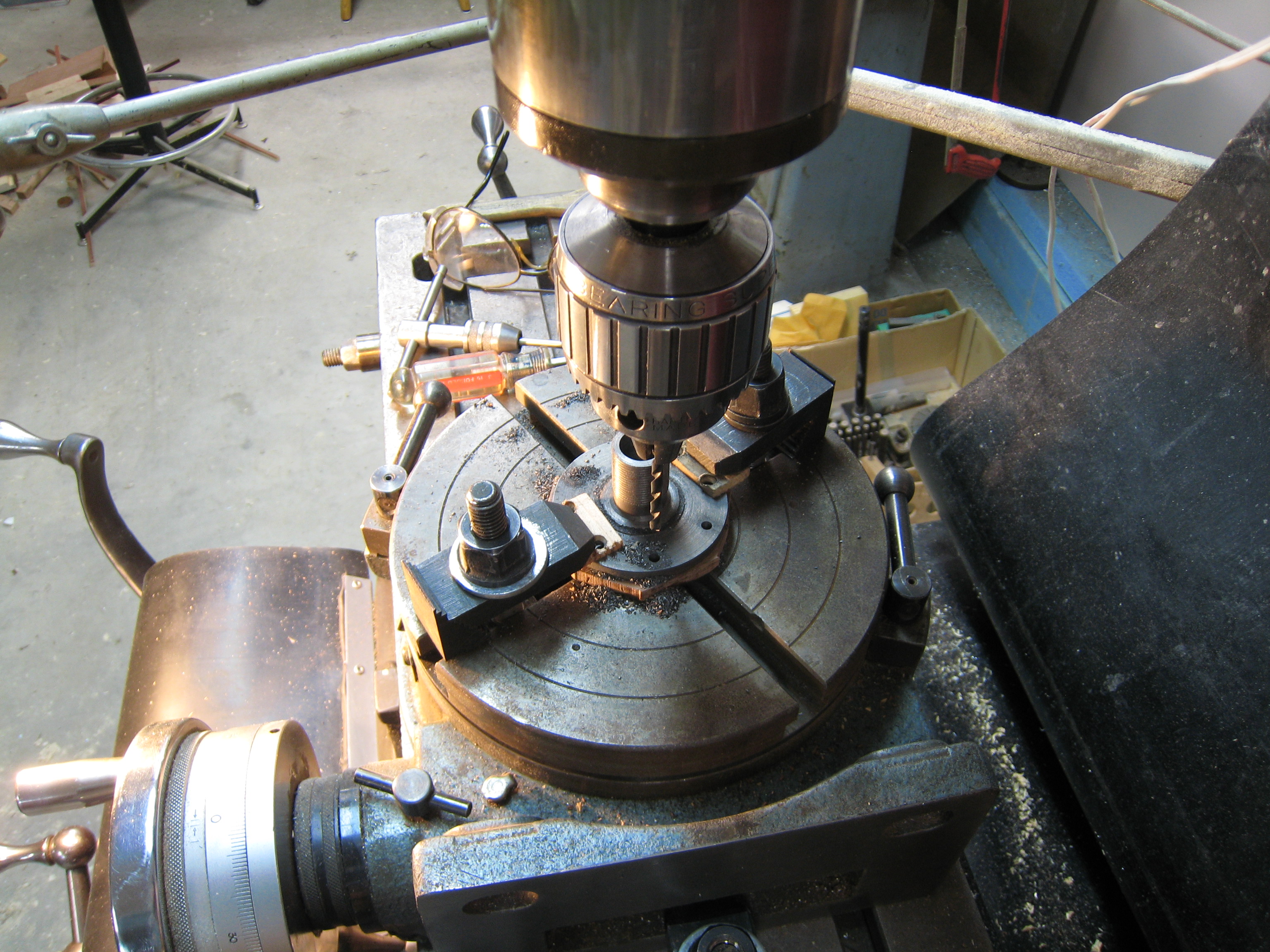
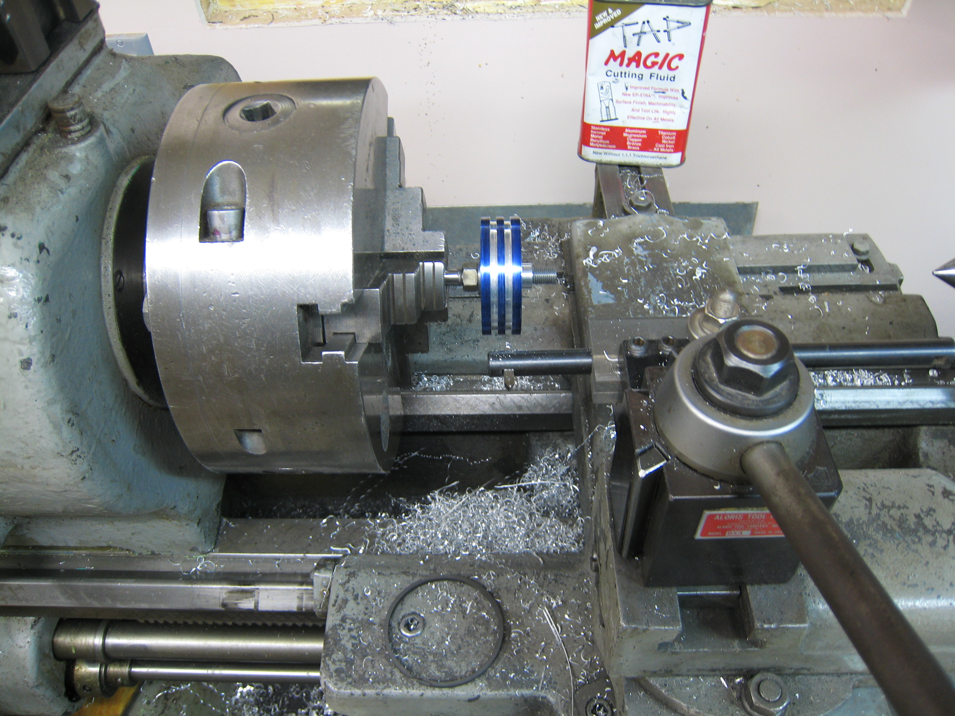
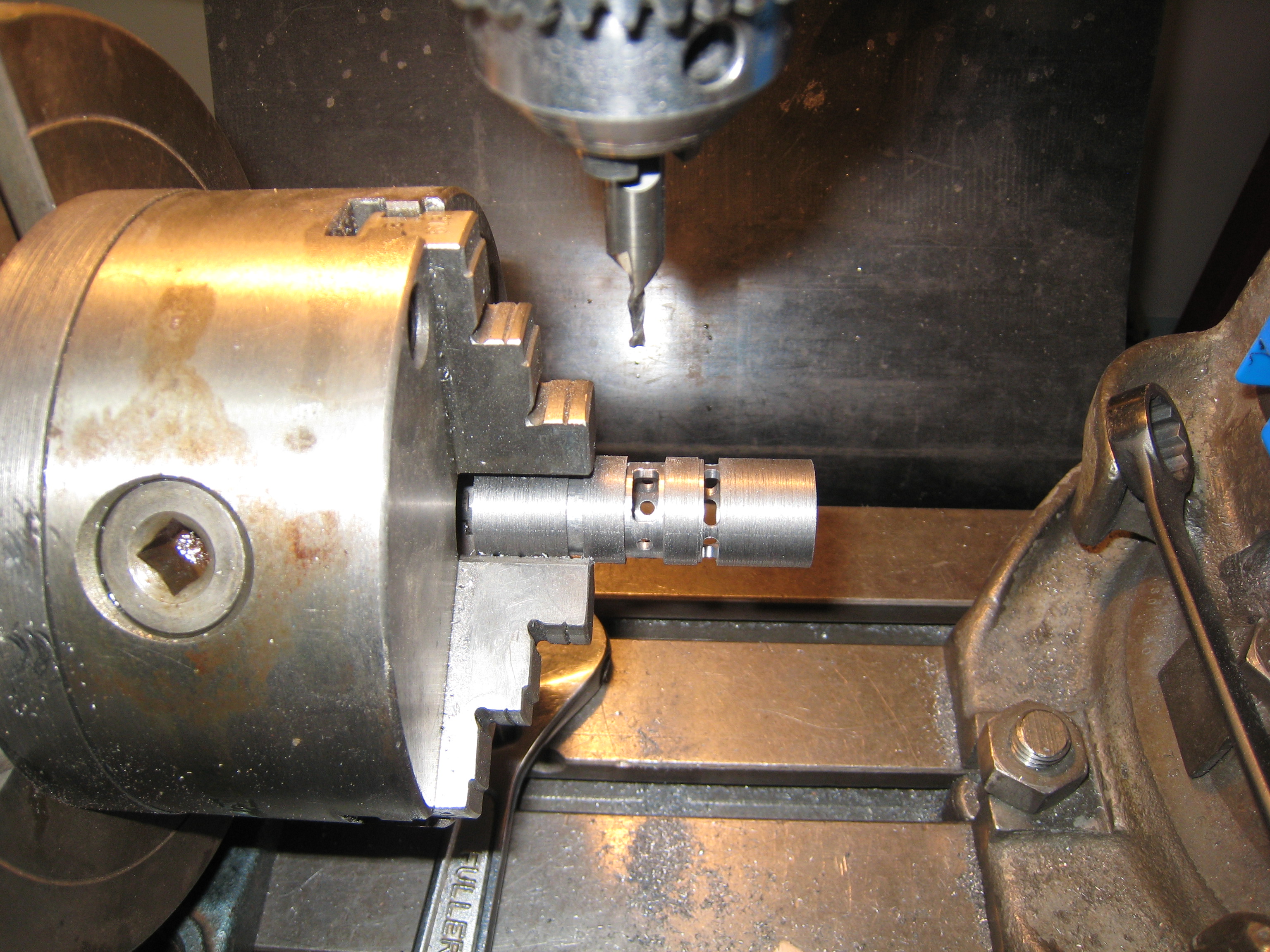
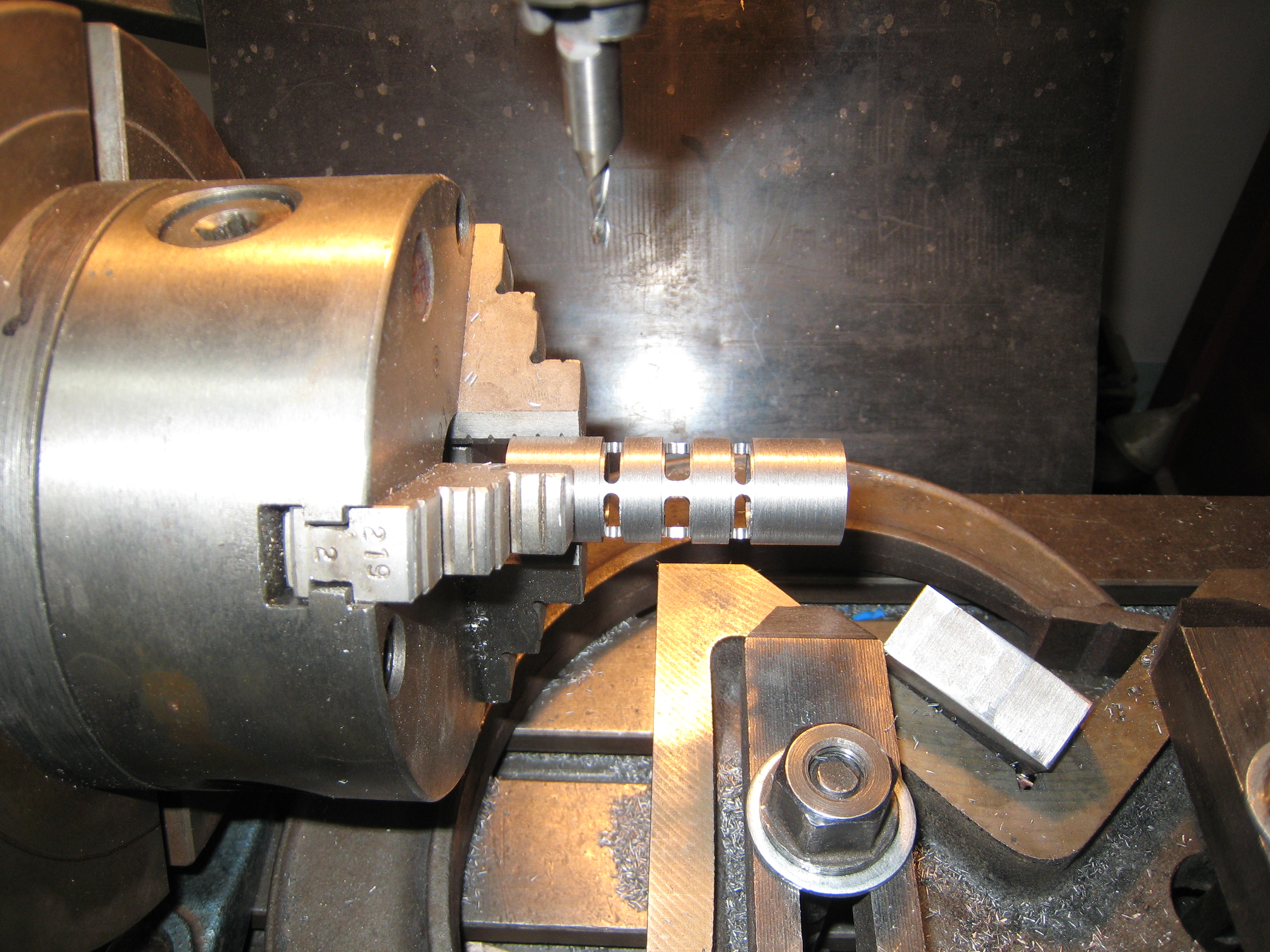
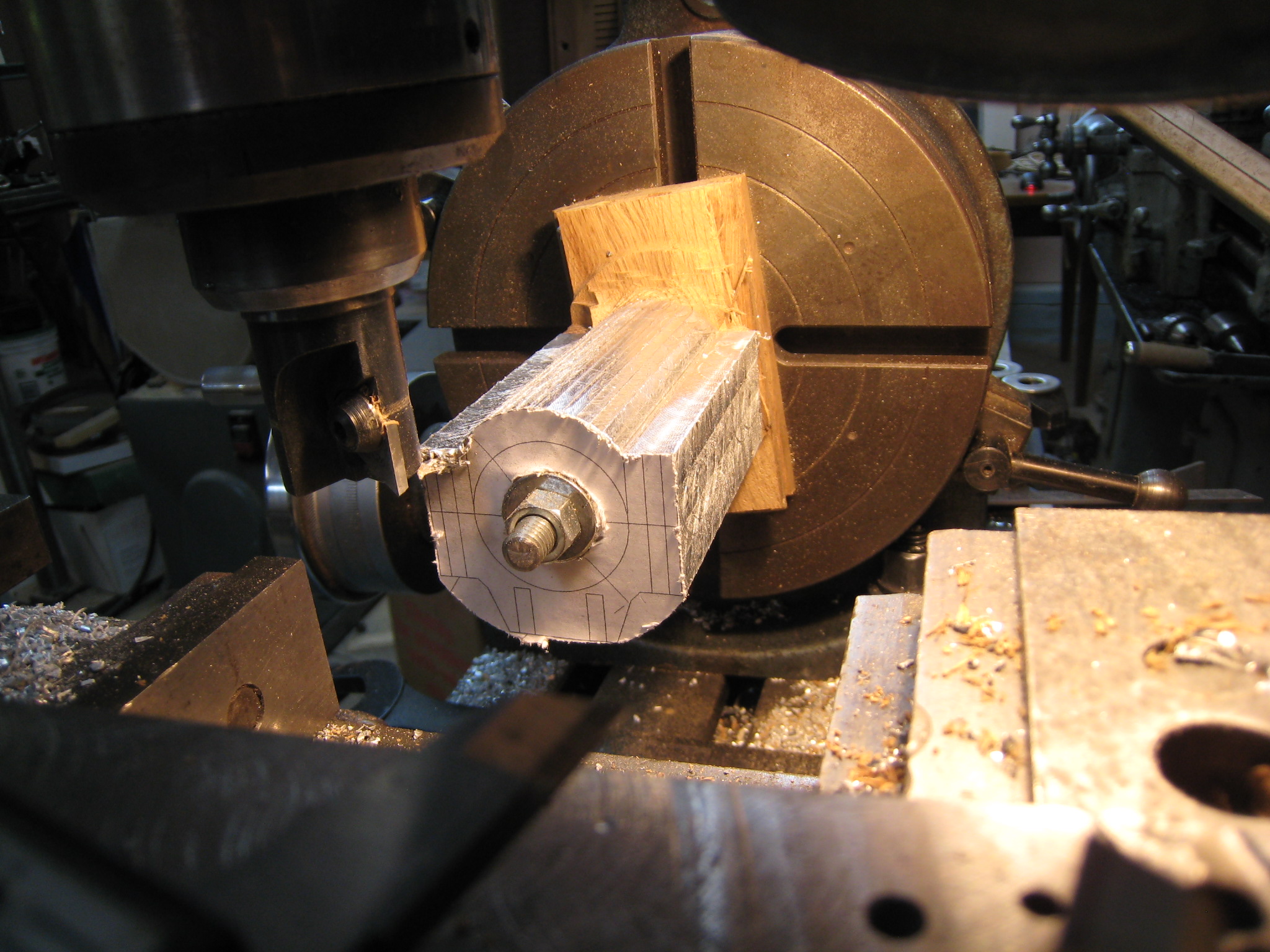
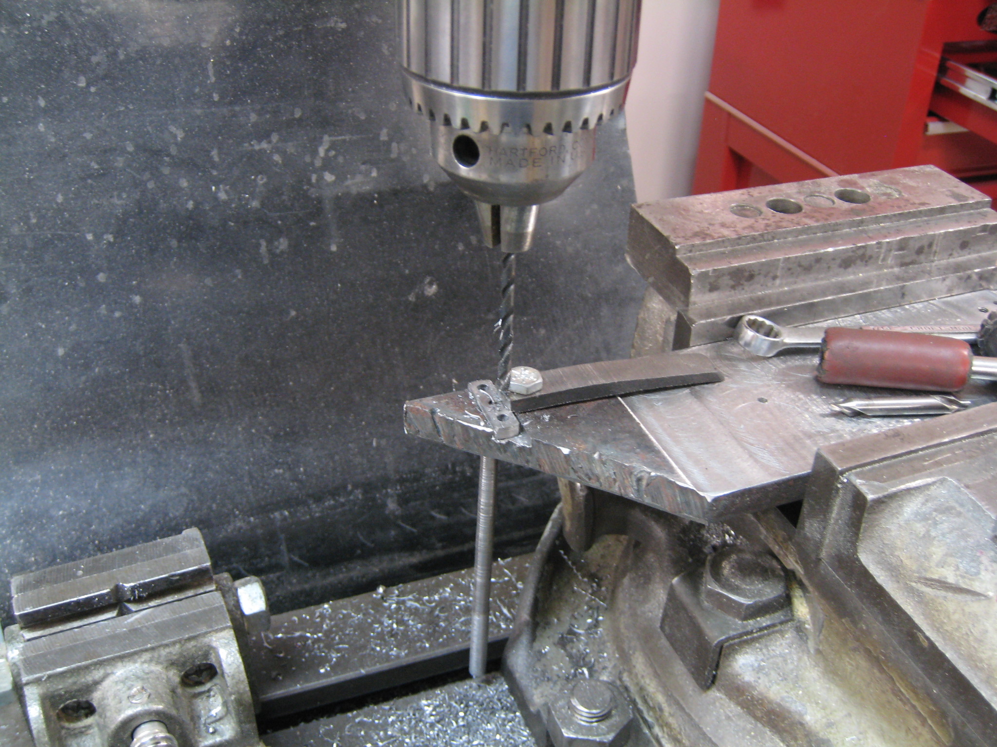
First, I put a threaded rod through the core hole and centered the crosshead tube using a 4 jaw chuck.
The treaded rod was prepared for the live center to stabilize the top of the standard.
I trued up both ends of the crosshead tube while chucking the last 1/4" of the stub at the bottom of the Standard.
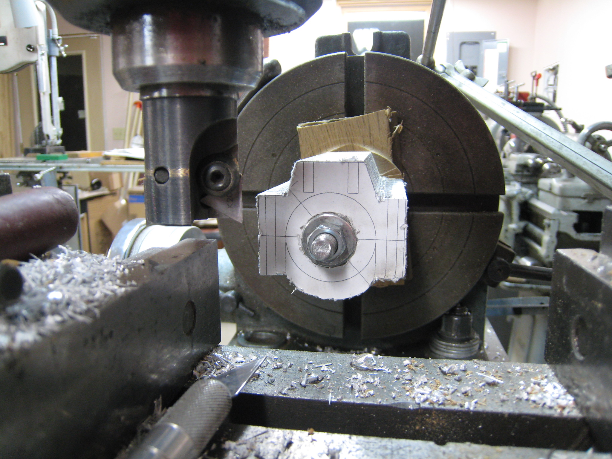
At this point, I machined the exposed part of the stub to about 7/8".
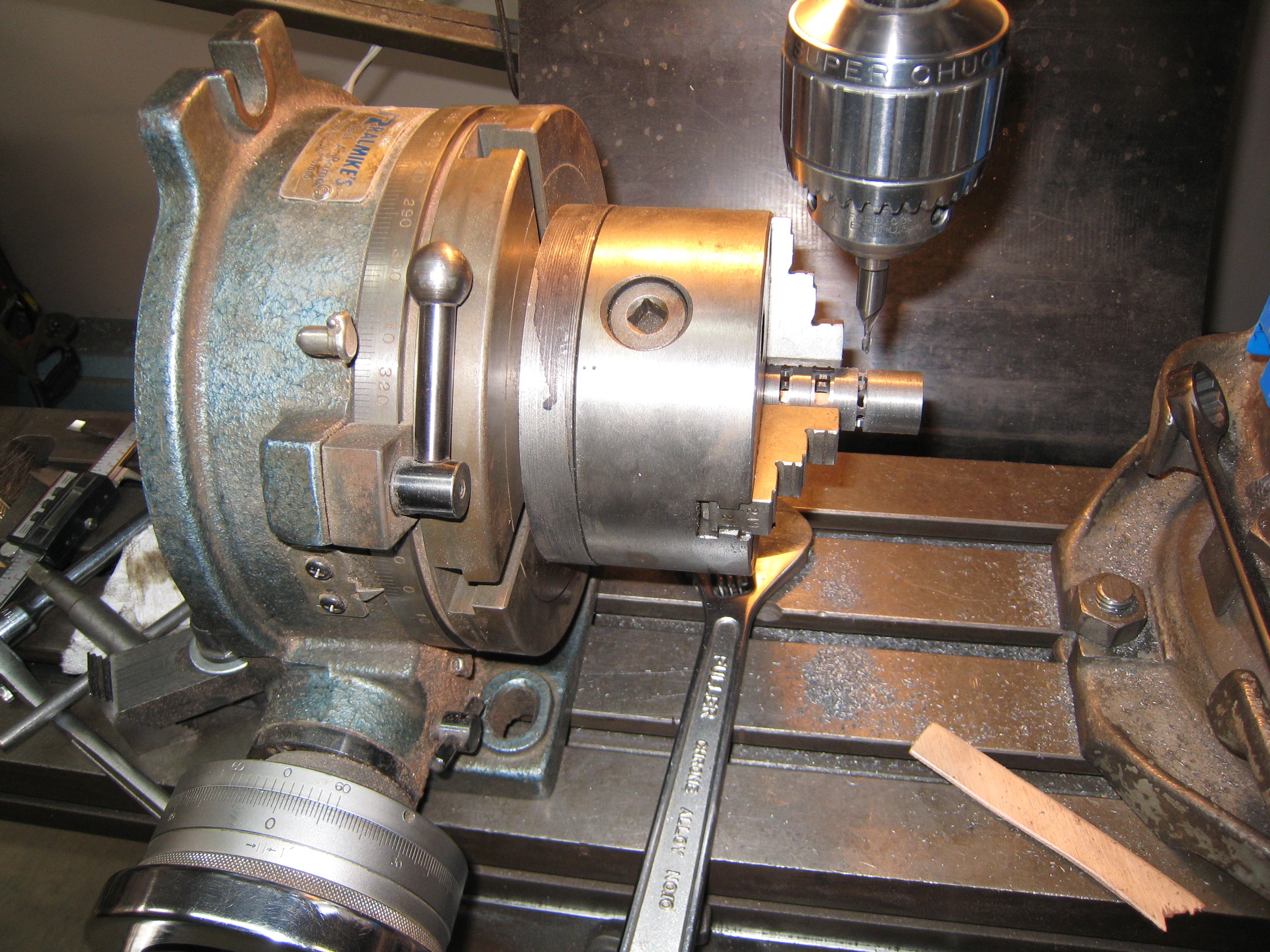
In the same setup, I machined the OD of the top of the Standard to be the same diameter as the cylinder.
Next I cut off the part of the stub that had been in the 4 jaw chuck leaving a 7/8" stub.
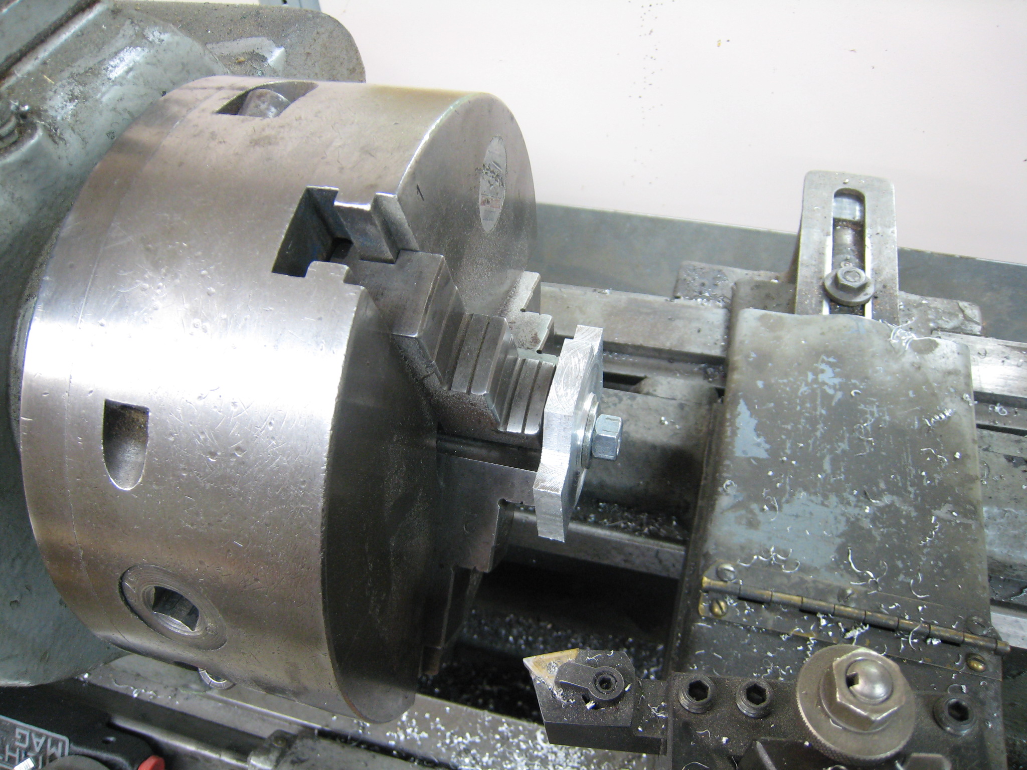
Now I could mount the Standard in a 7/8" collate and use the steady rest on the machined top of the Standard.
It is important to make sure that the steady rest is not pulling the top of the Standard off center in any direction as this will make the cross head guide bore into a cone.
Next I machined the feet of the Standard.
Next the steady rest is removed and the carriage moved out beyond the Standard.
The steady rest is then remounted without changing the setting.
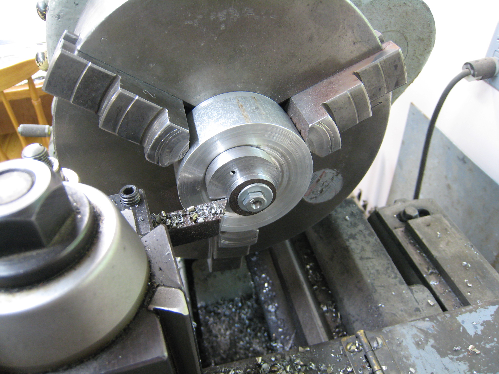
The cross head guide and top of the Standard can now be bored/faced on the Standard.
Care must be taken to avoid vibration due to the intermittent cut when boring the cross head guide.
Fifty RPM should be slow enough to avoid any visible signs of vibration.
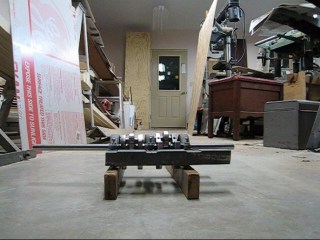
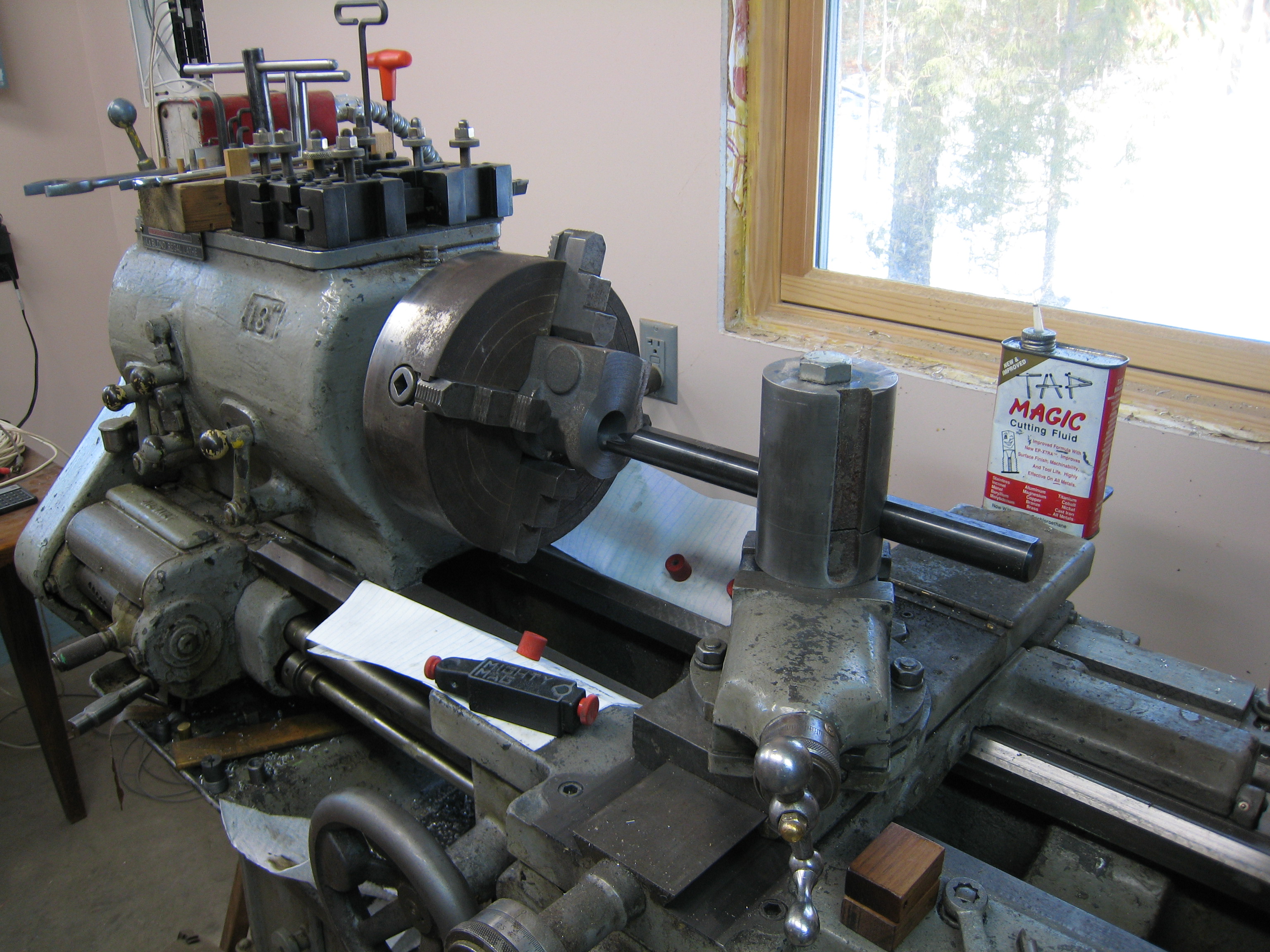
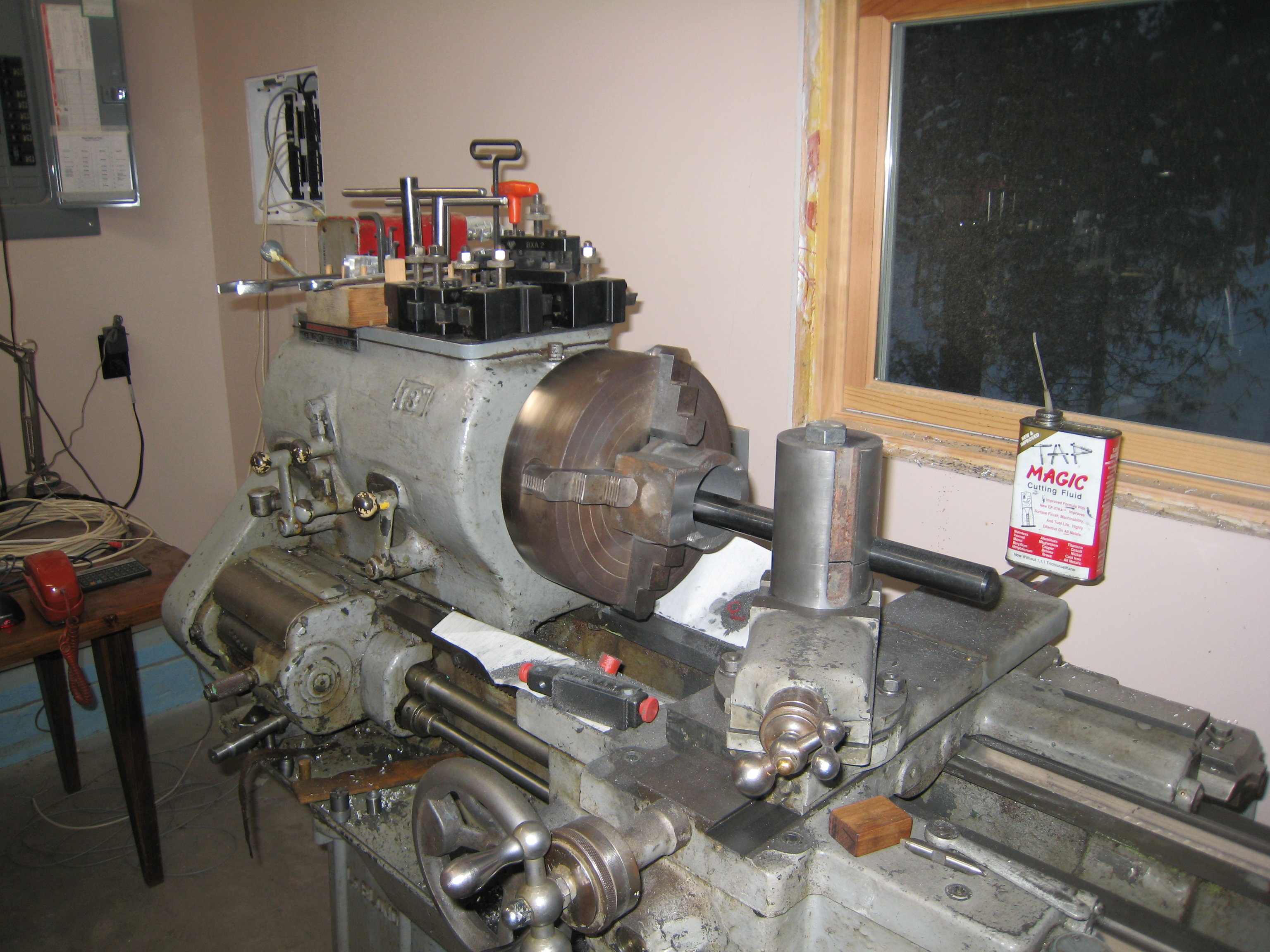
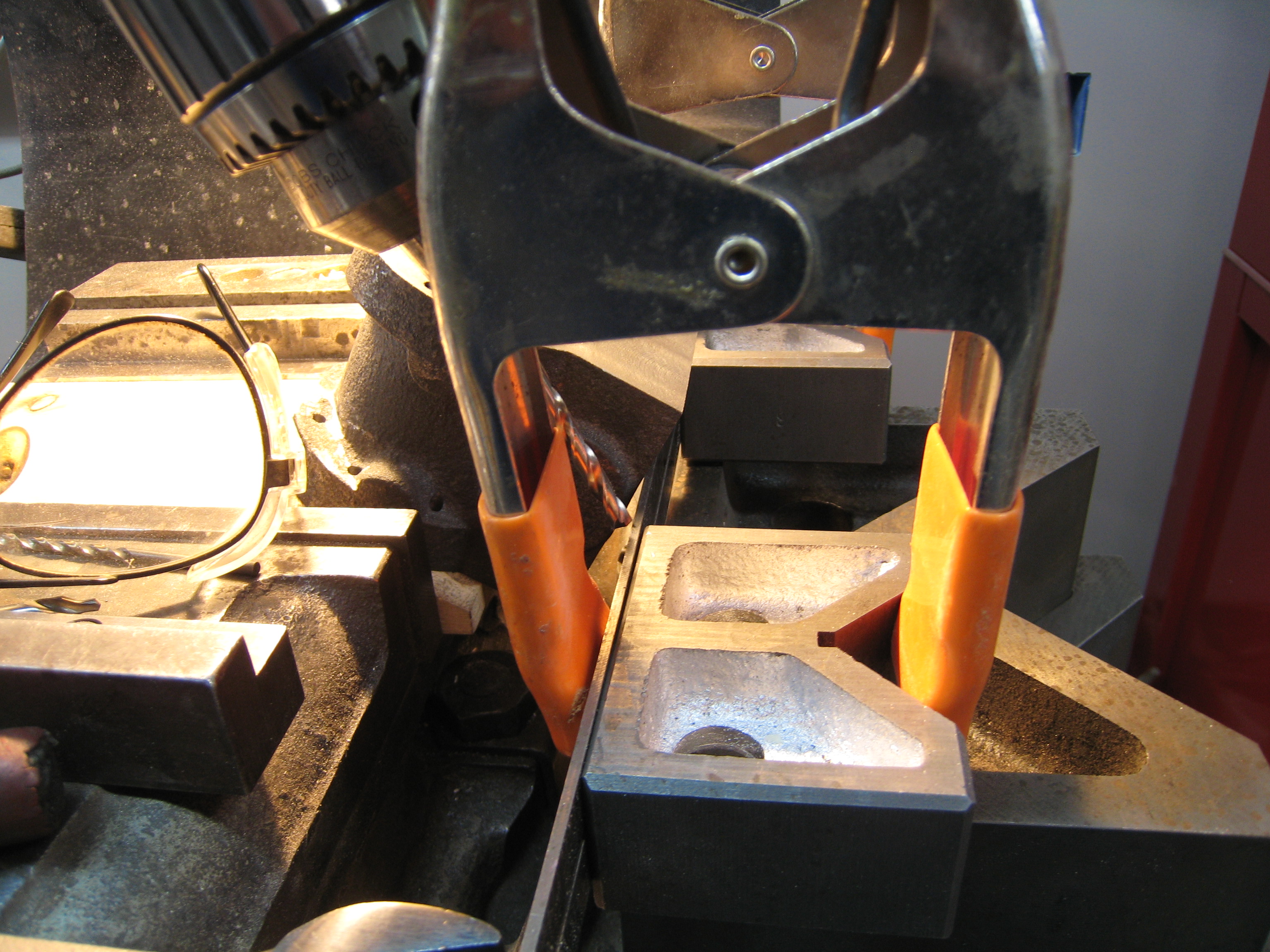
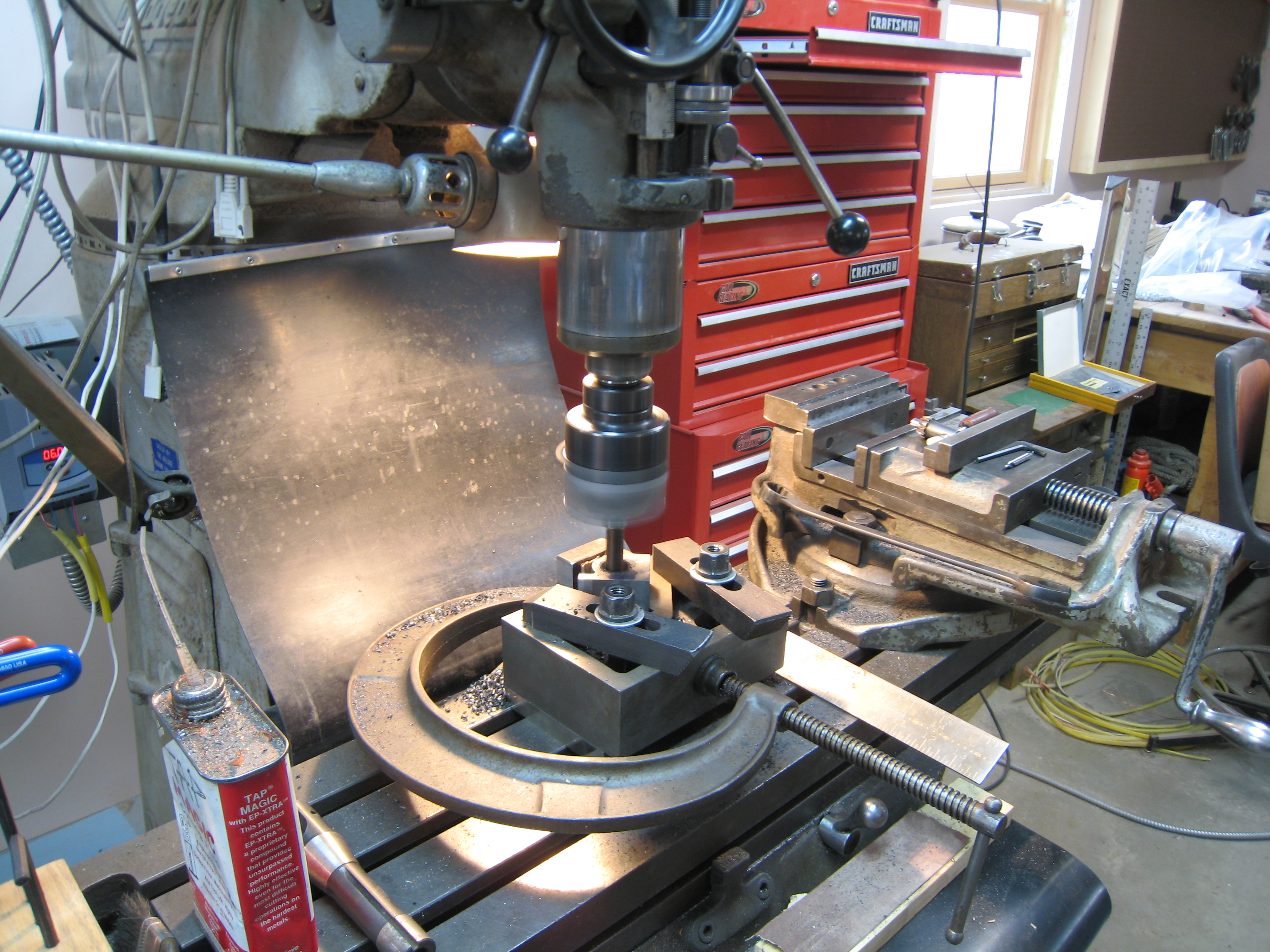
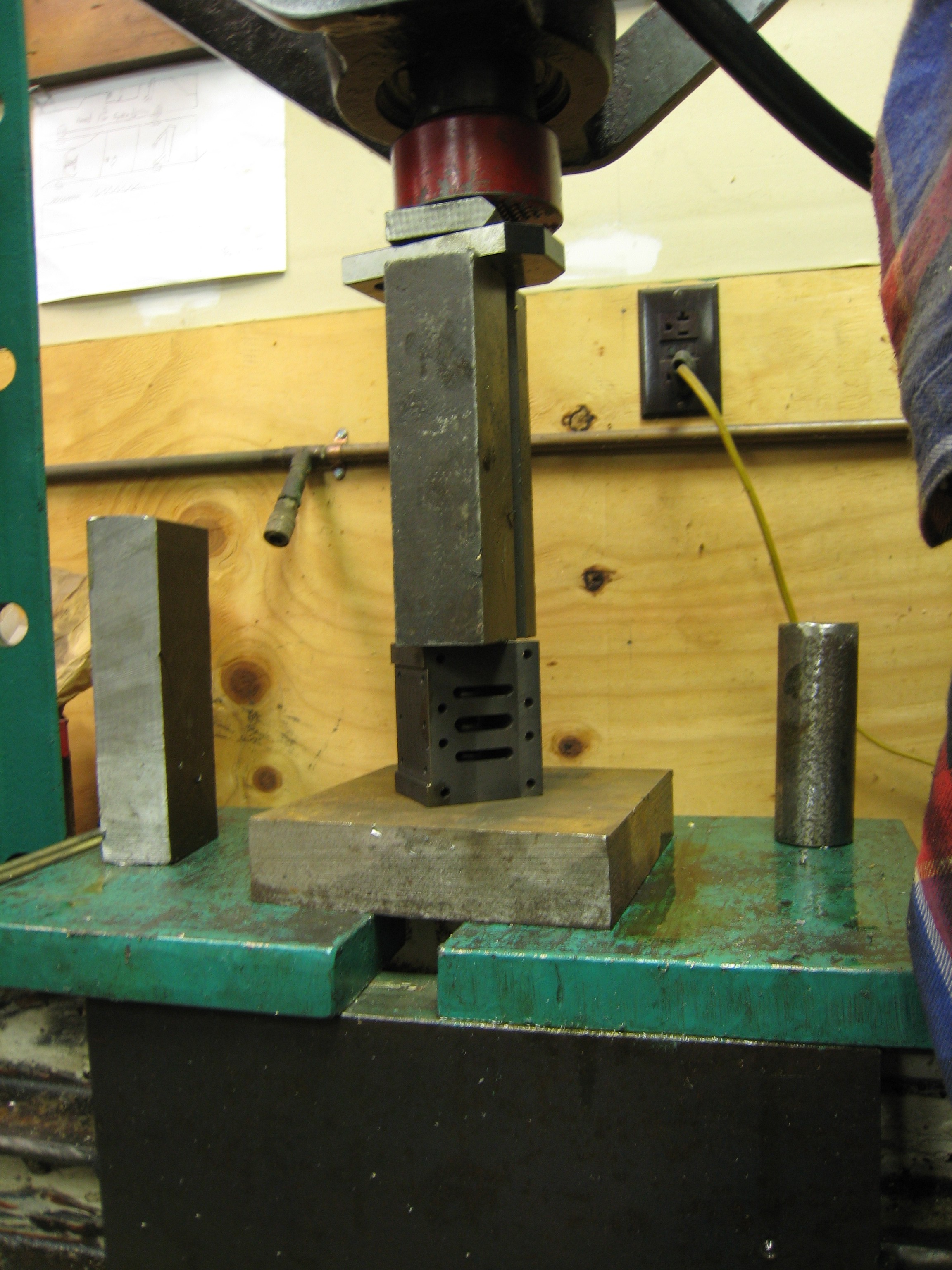
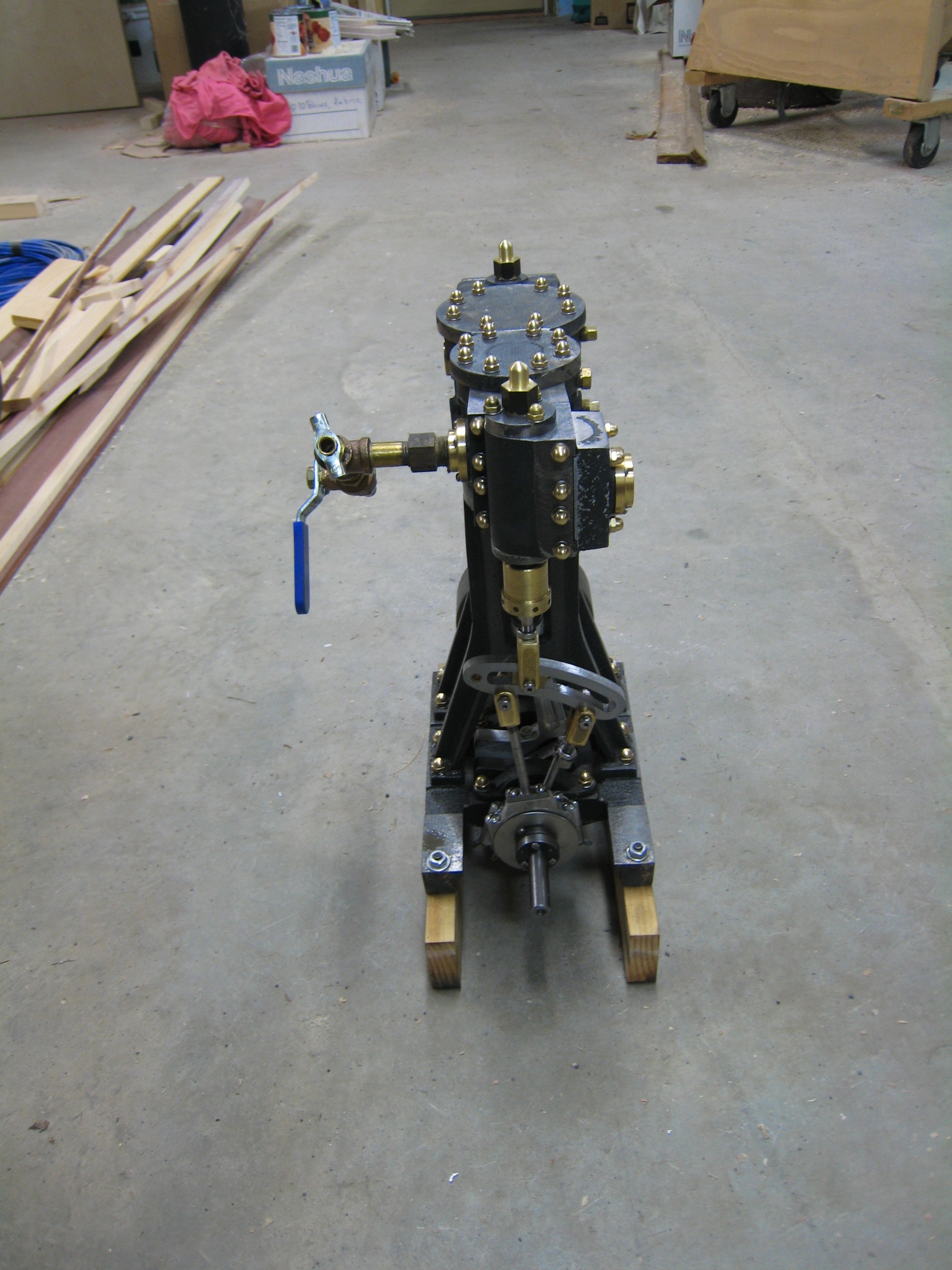
Standard Setup (1/12/2008)
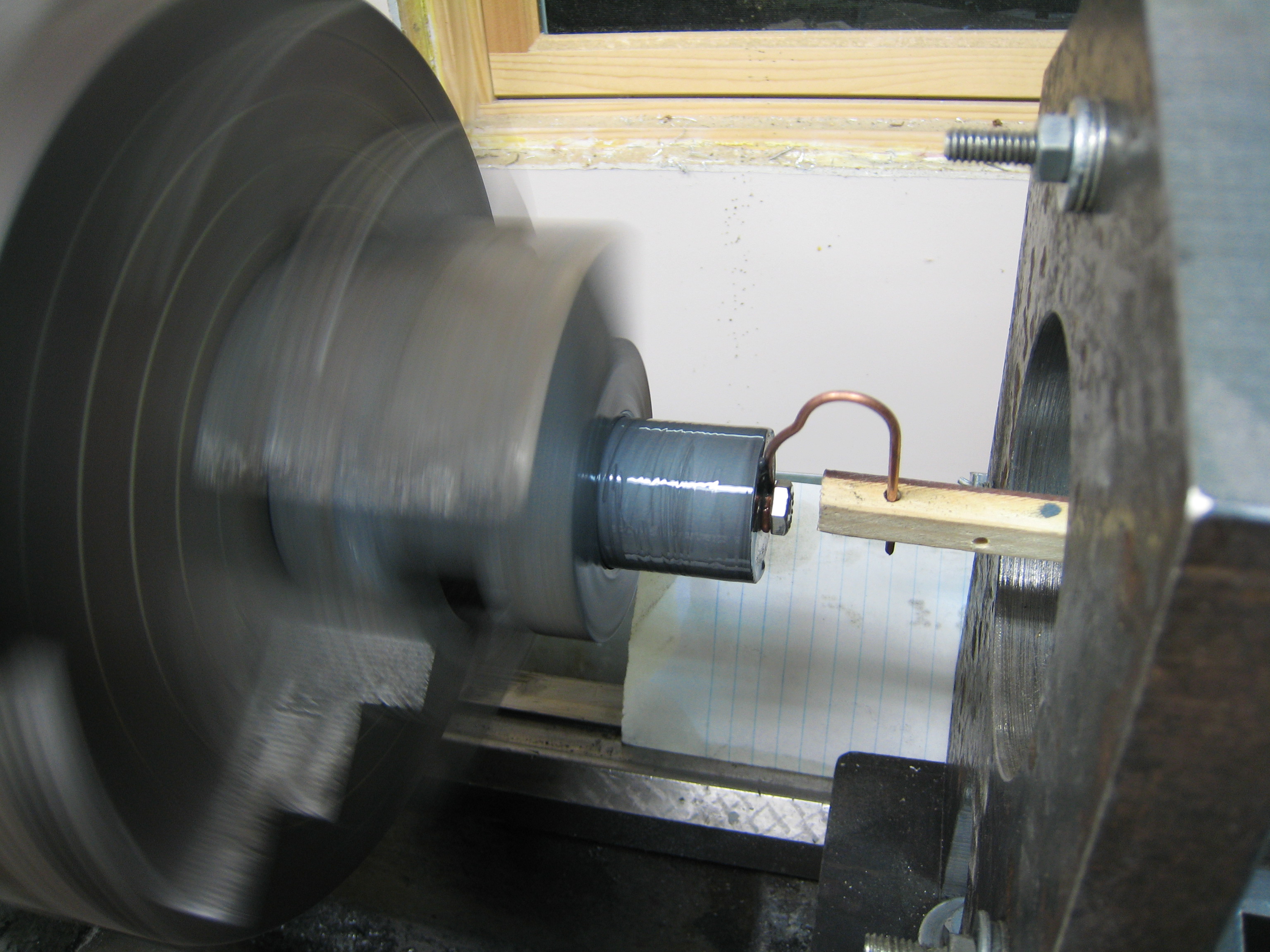
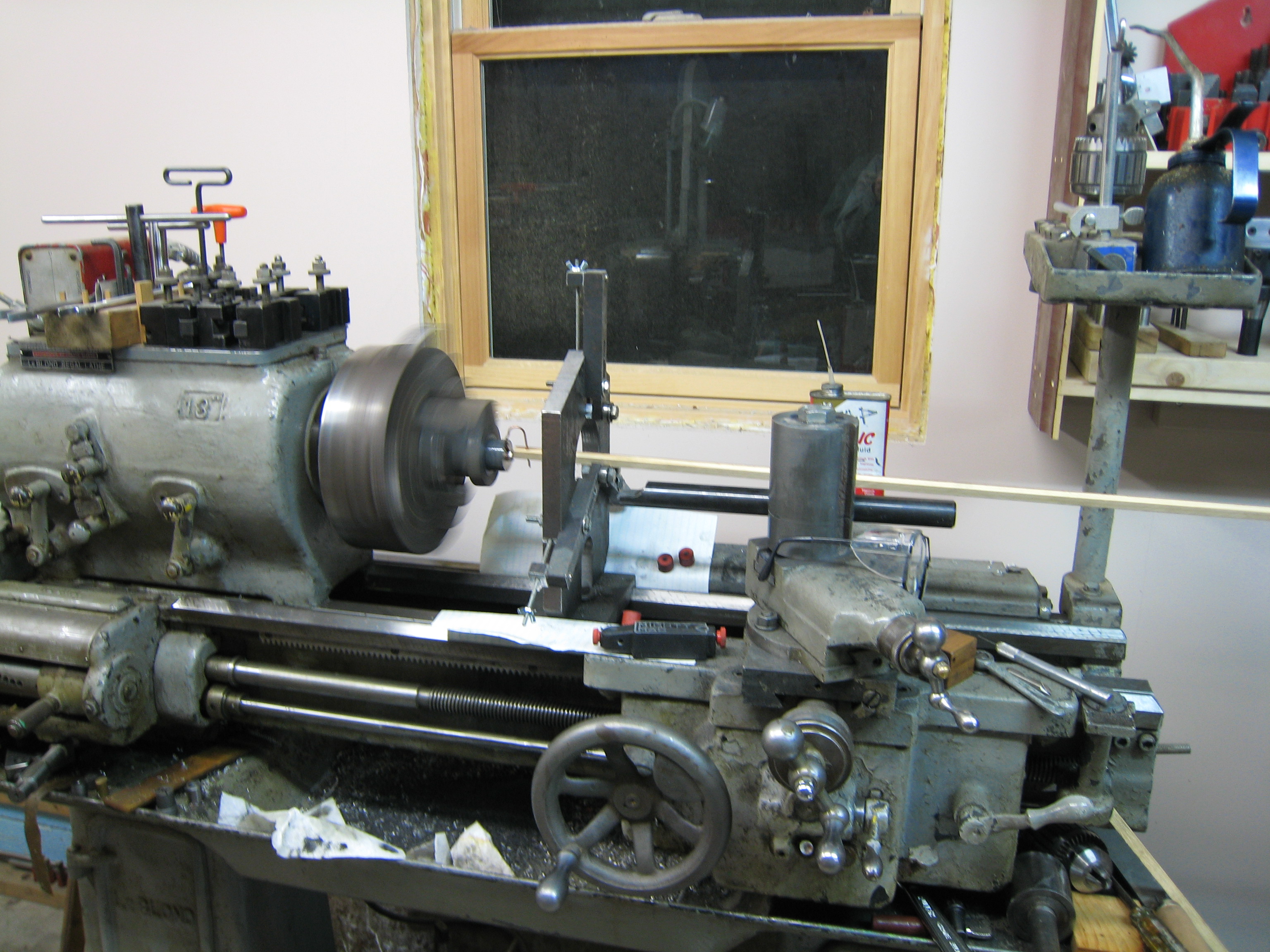
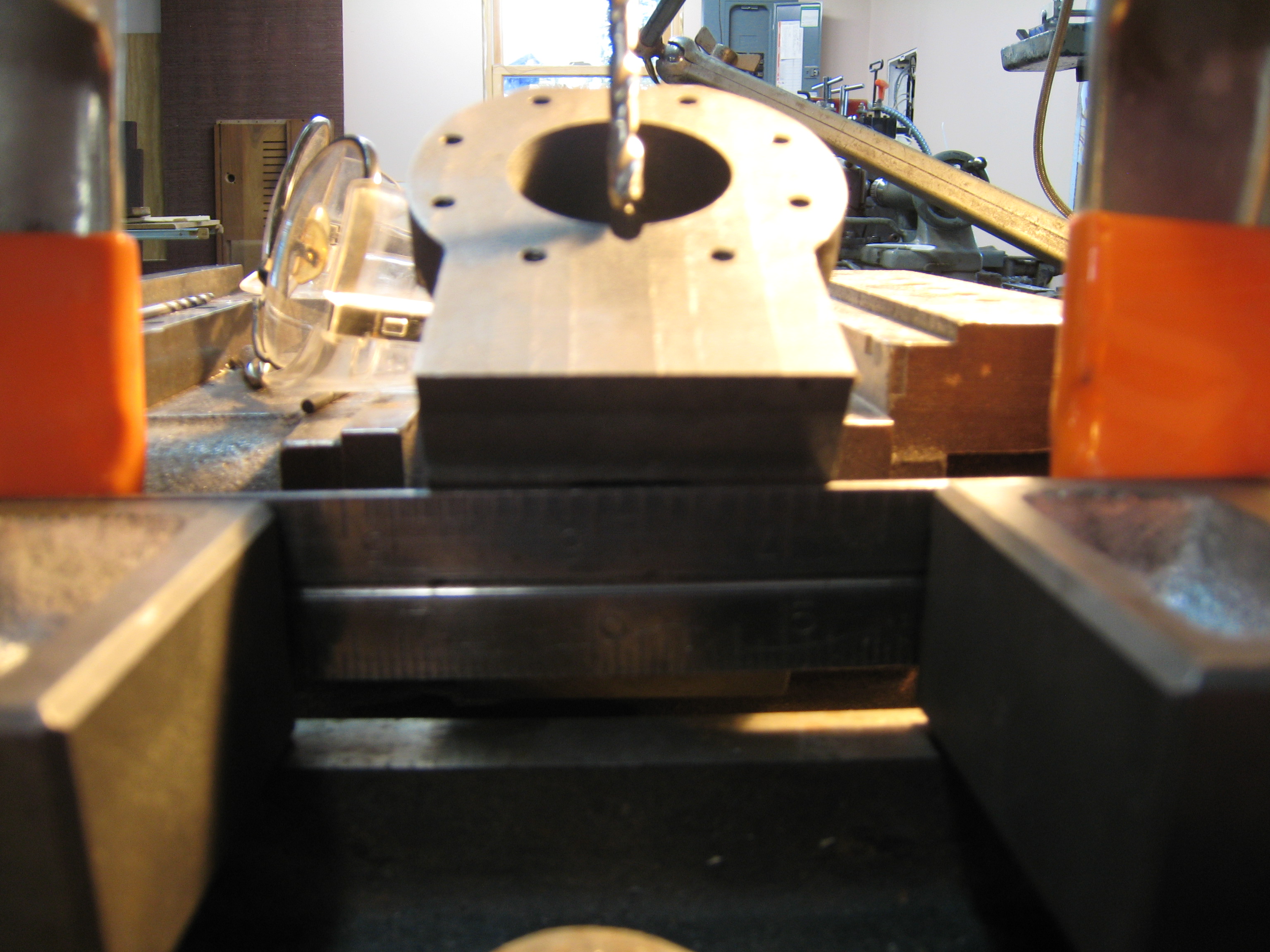
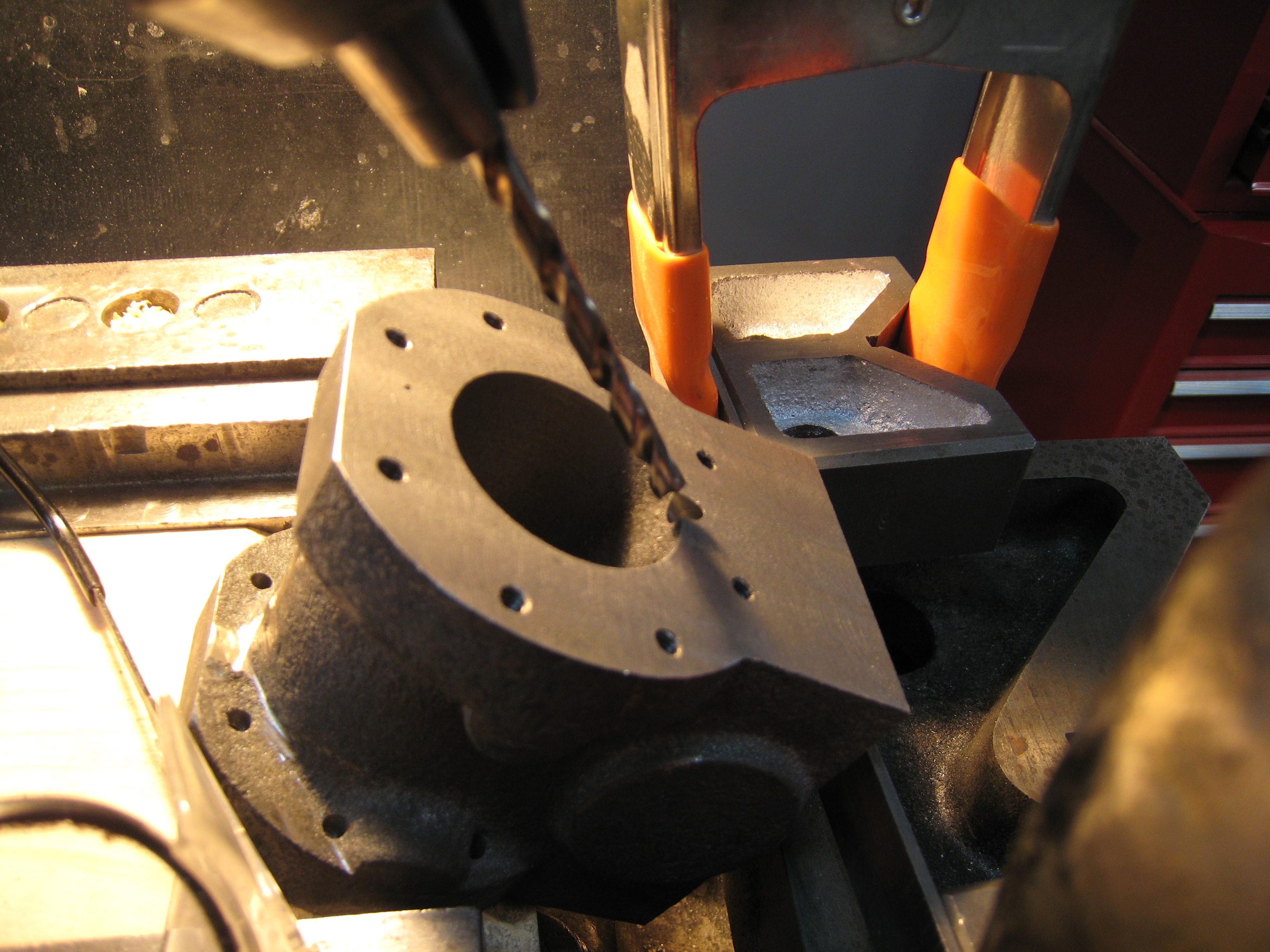
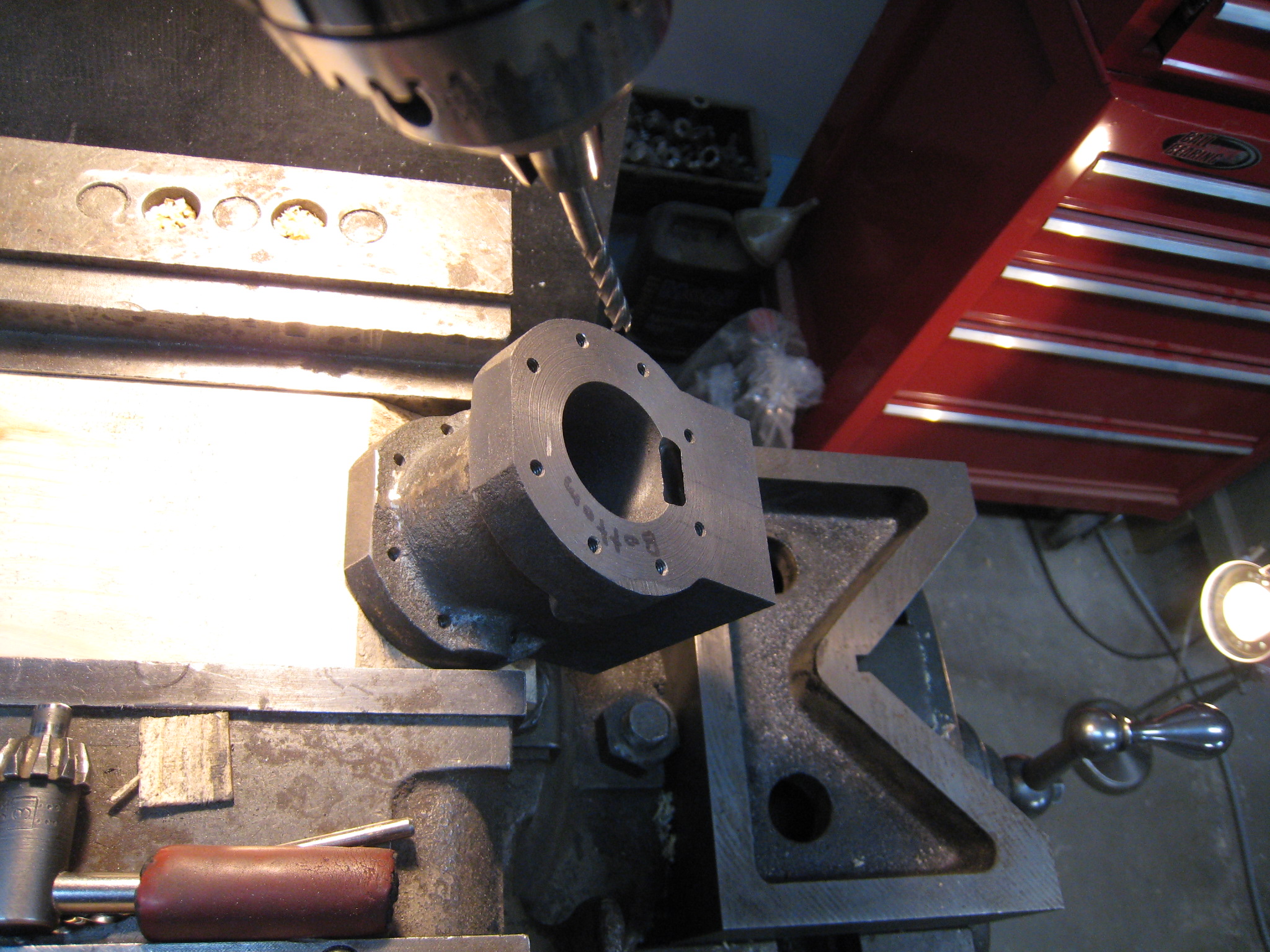
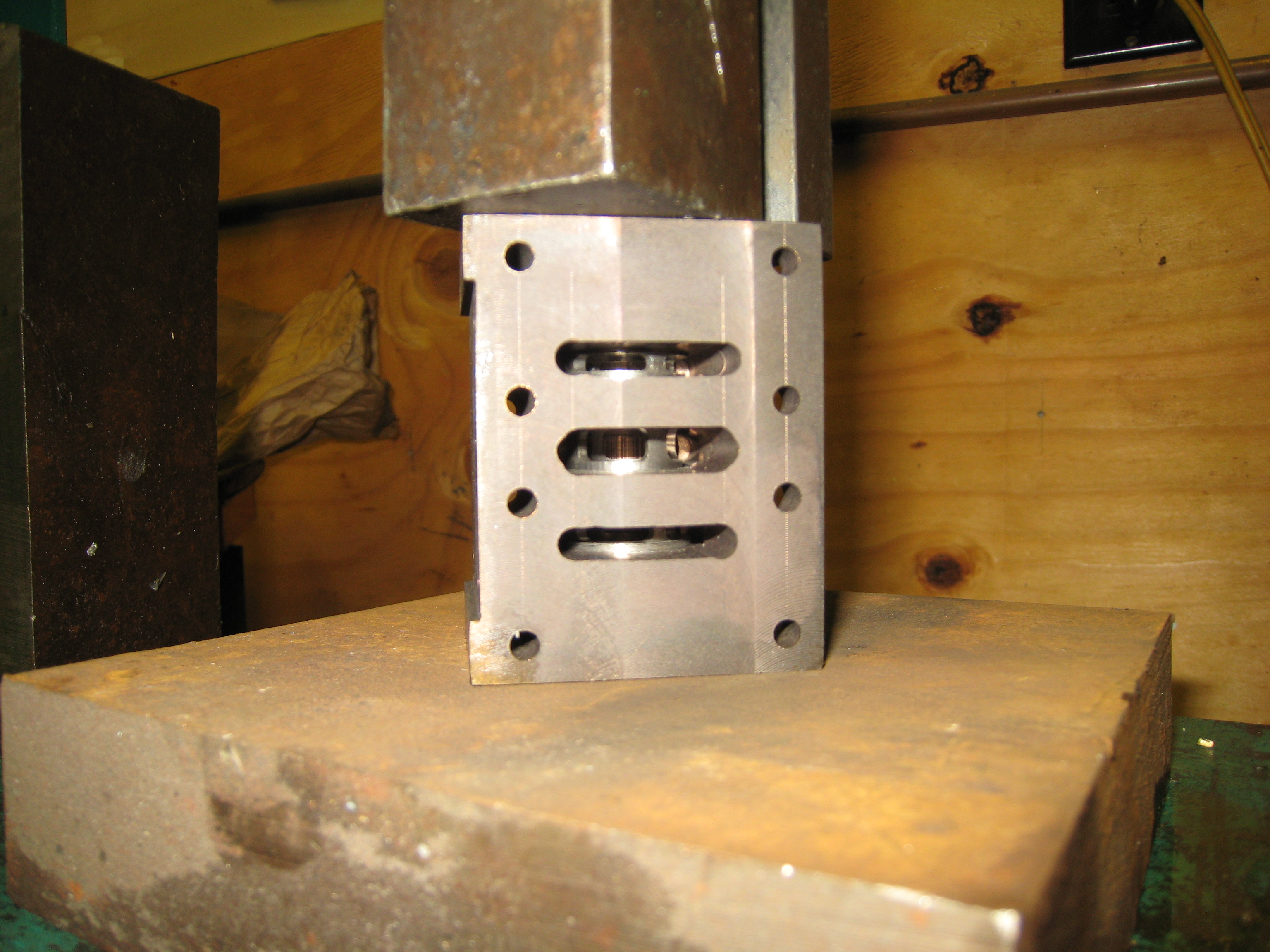
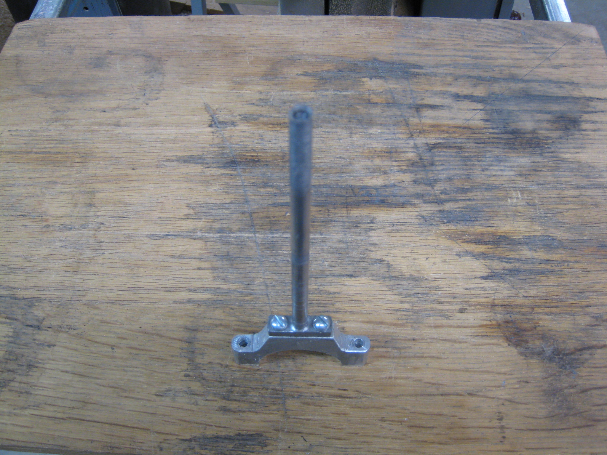
Bored Standard (1/17/2008)
Bored Standard (1/17/2008)
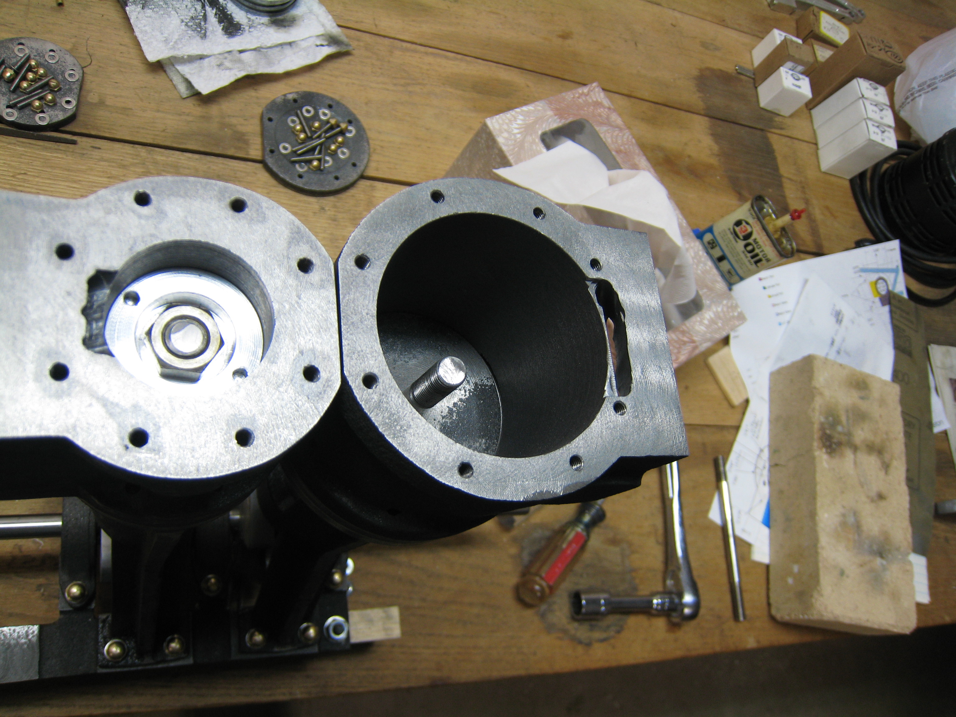
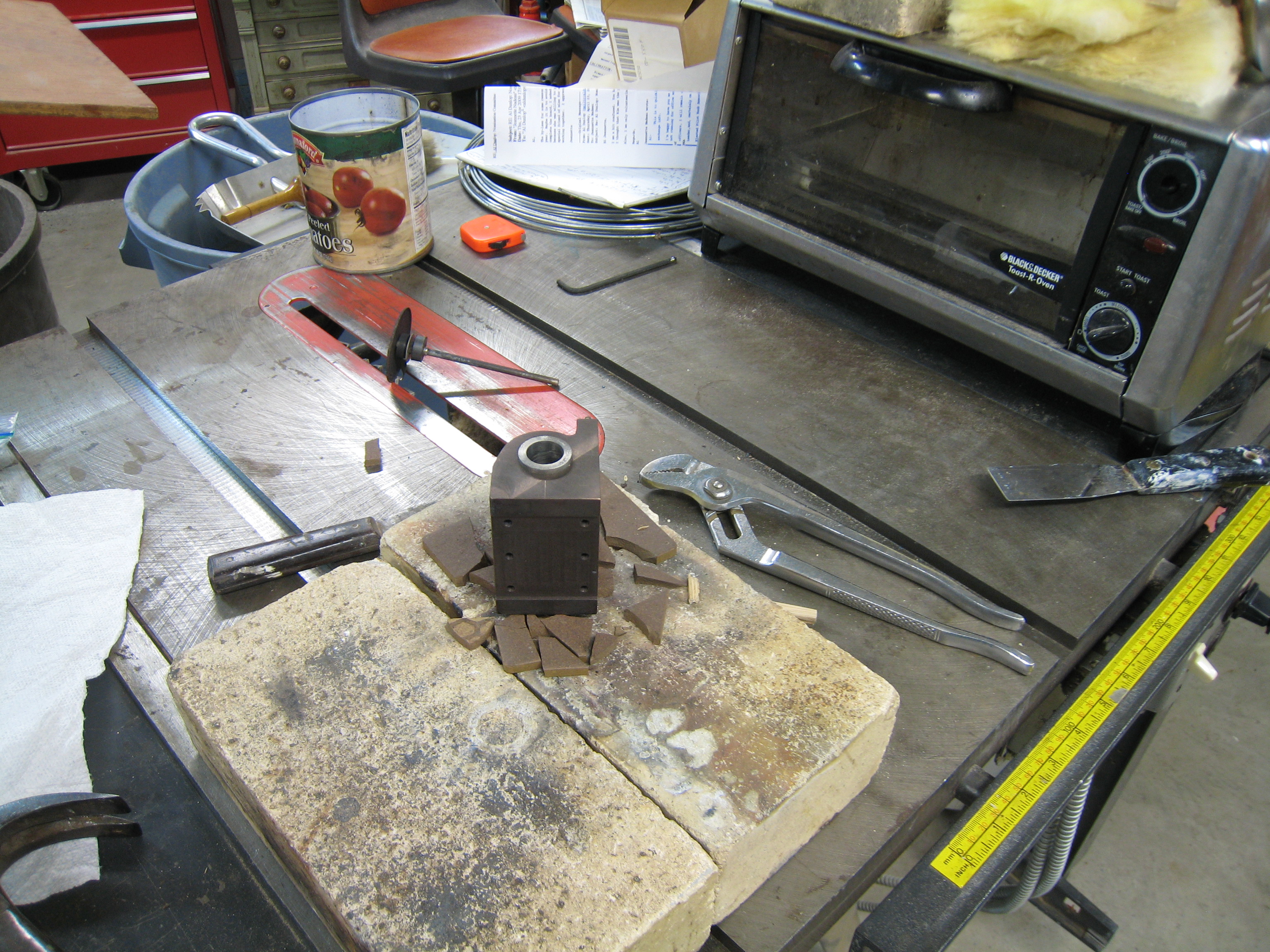
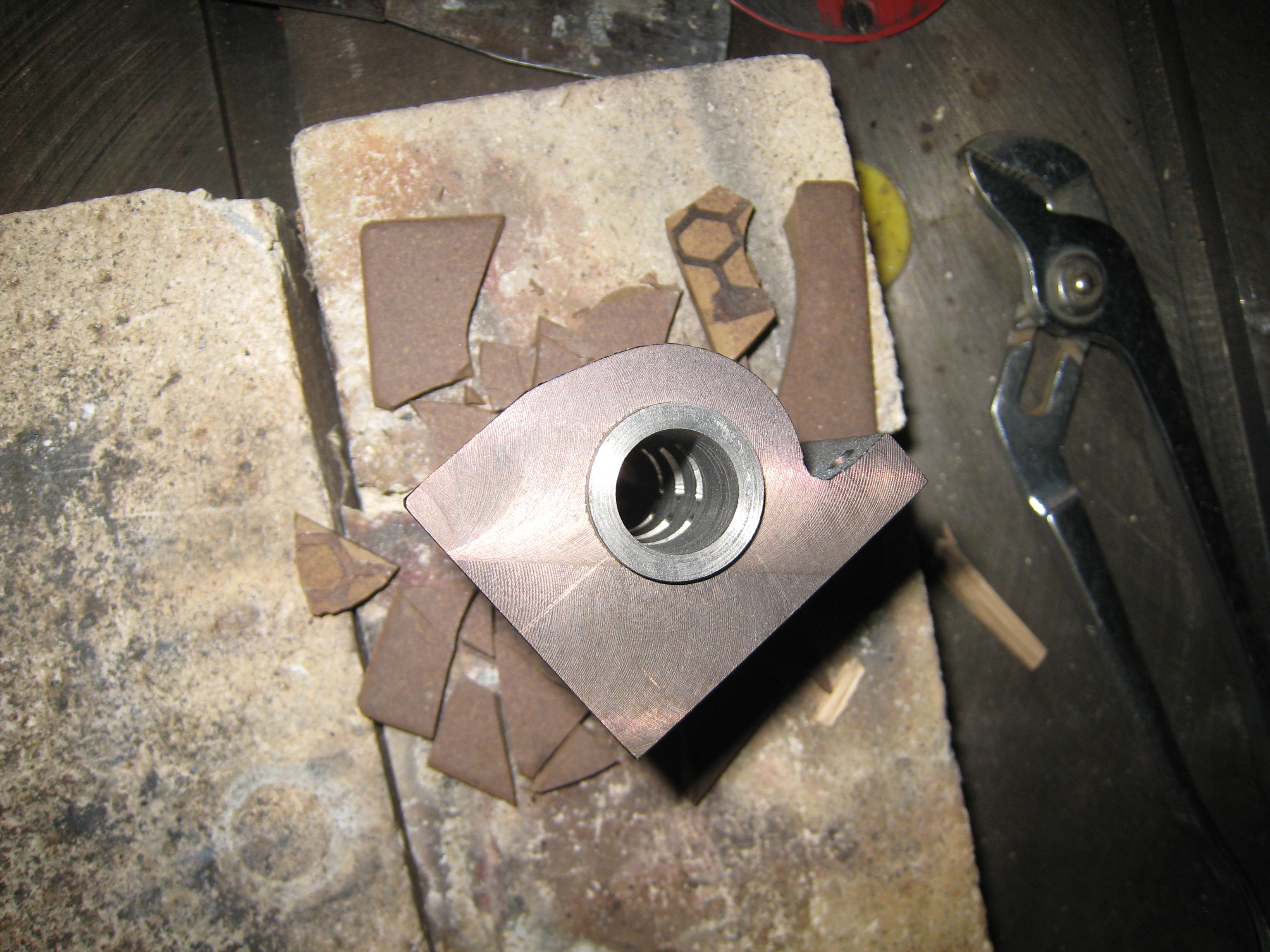
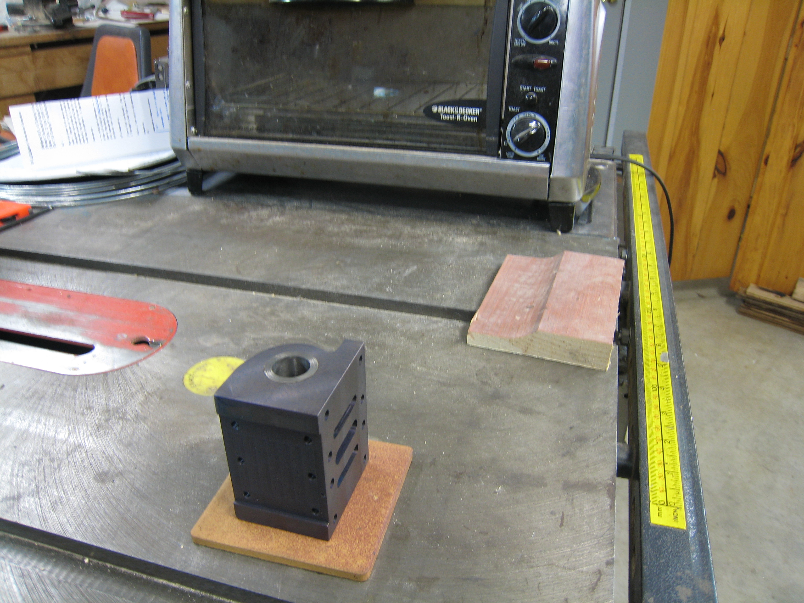
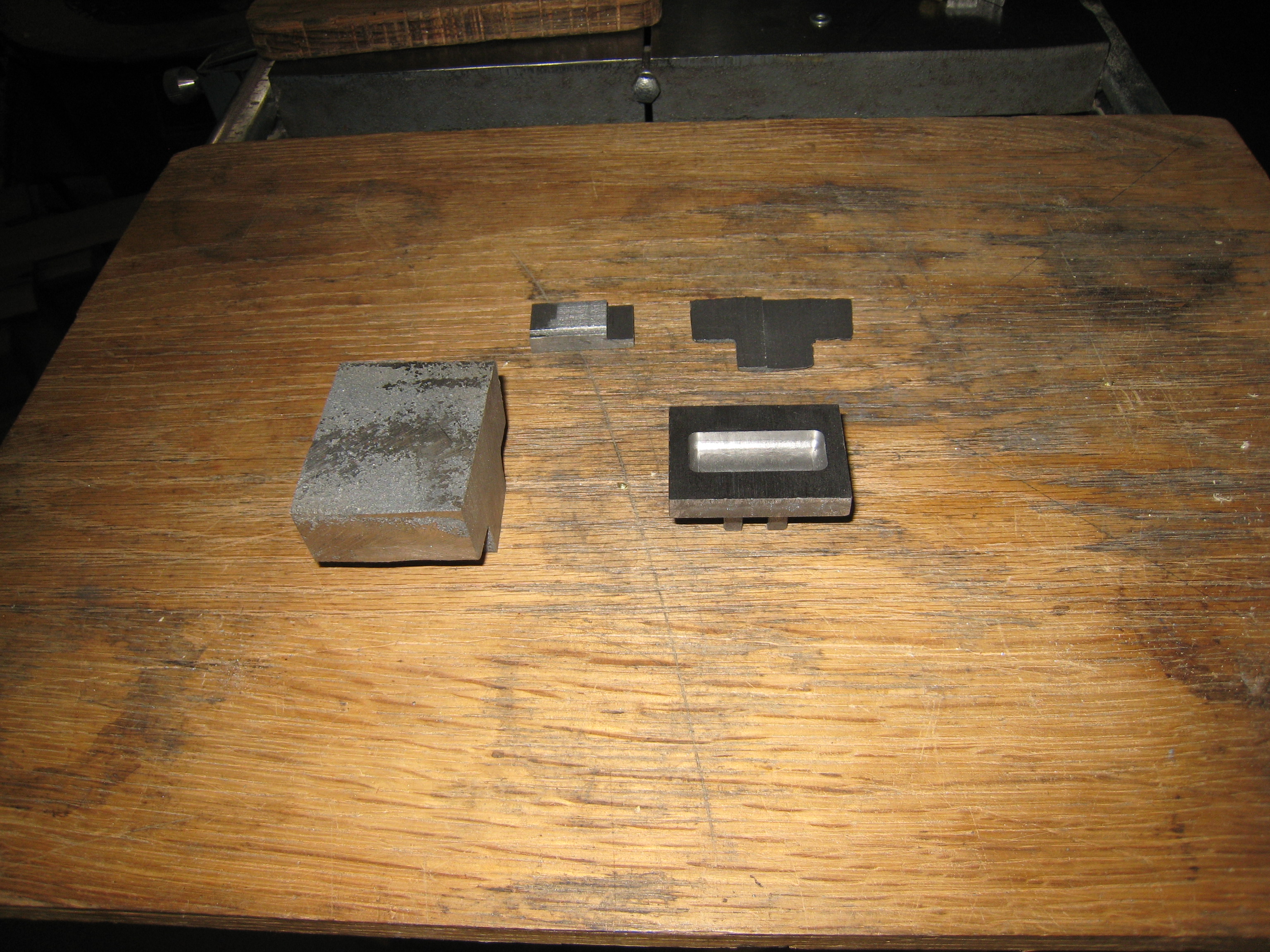
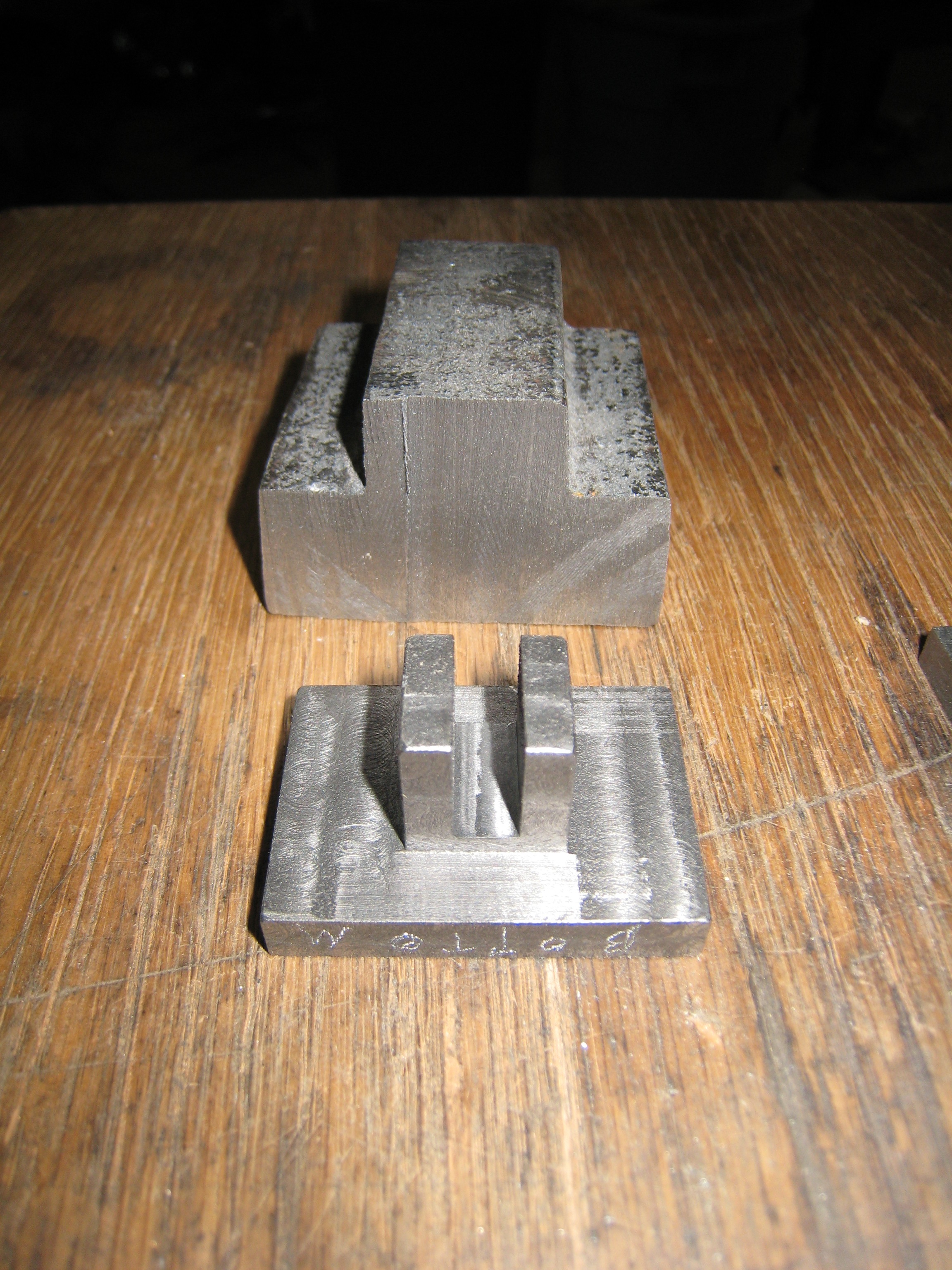
Base
The base is the part that ties the engine together.
It dies not have complicated machining operations.
But the accurate of the alignment of the bearing pockets is very important.
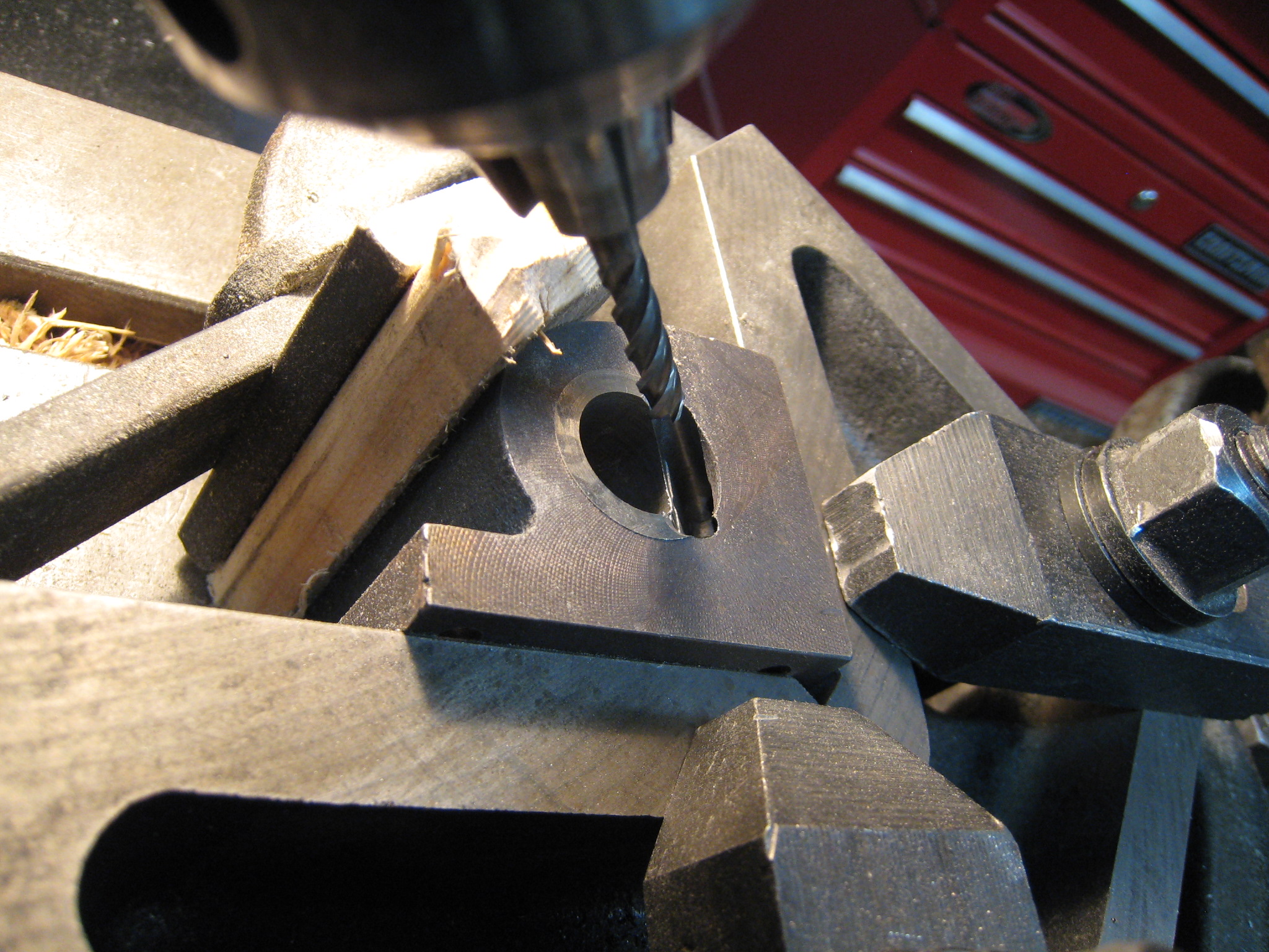
Once again a long boring bare is needed to reach in to the third bearing.
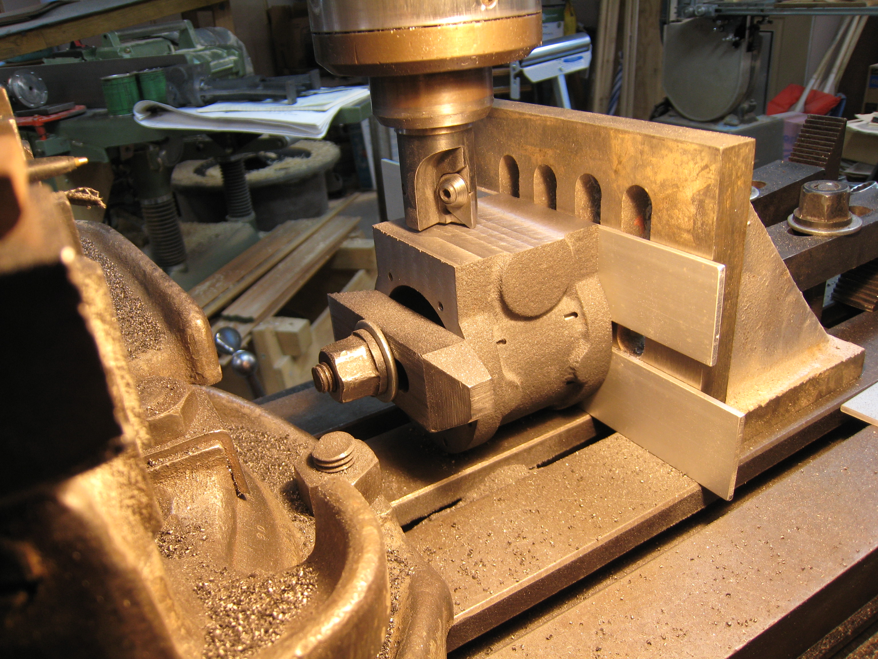
With the base upside down, there will probably be two opposite corners that rock back and forth. Shim these corners with the same amount of shim stock until the rocking stops. Clamp the other two corners before surfacing the bottom of the base. The top of the base is then surfaced as seen in the left picture below.
In my case the covers had some hard spots on the bottom.
The base also had some hard edges on the ends where the arms for the pumps stick out.
Although the foundry had said that they were pouring 750 pound items from the same pot and to let them know if anything was a problem and they would remake the part(s), I decided to see if I could just go ahead and do the machining.
Carbide is clearly much better than cobalt for hard spots.
Base done with an cobalt end mill There is a 0.02" variation in the surface (3/1/2008)
Base done with a carbide surfacer(?) (3/17/2008)
Baring caps done with a cobalt end mill (3/1/2008)
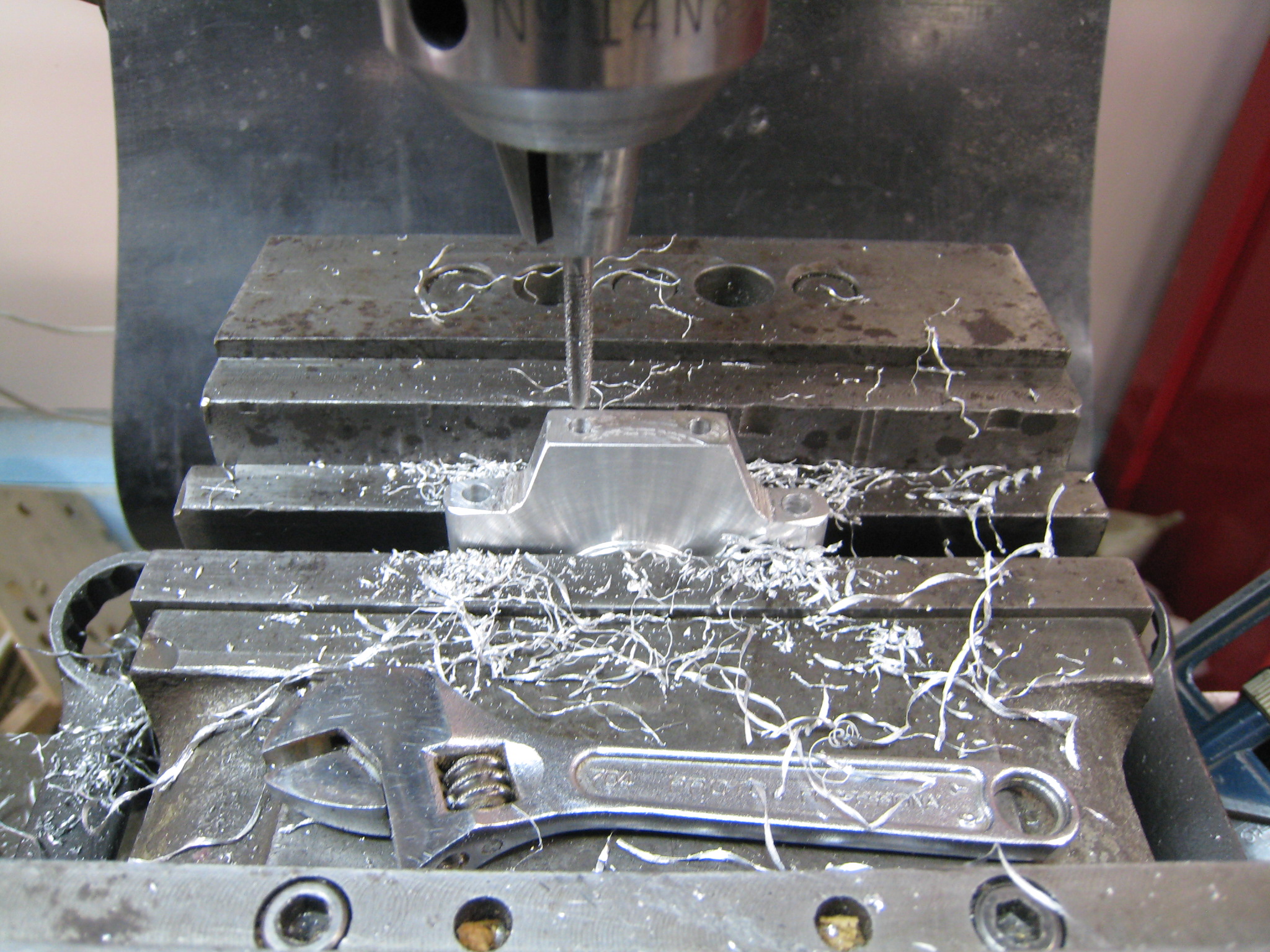
The bearing pockets were bored in a single operation as seen below.
The skilled machinist will know that everything must be firmly mounted or a catastrophe WILL occur.
Many light cuts were made during this operation.
(I was not able to find material to balance my face plate. At 50 RPM the off balance weight was usually greater than the cutting friction.)
Setup for boring the base bearing pockets (3/17/2008)
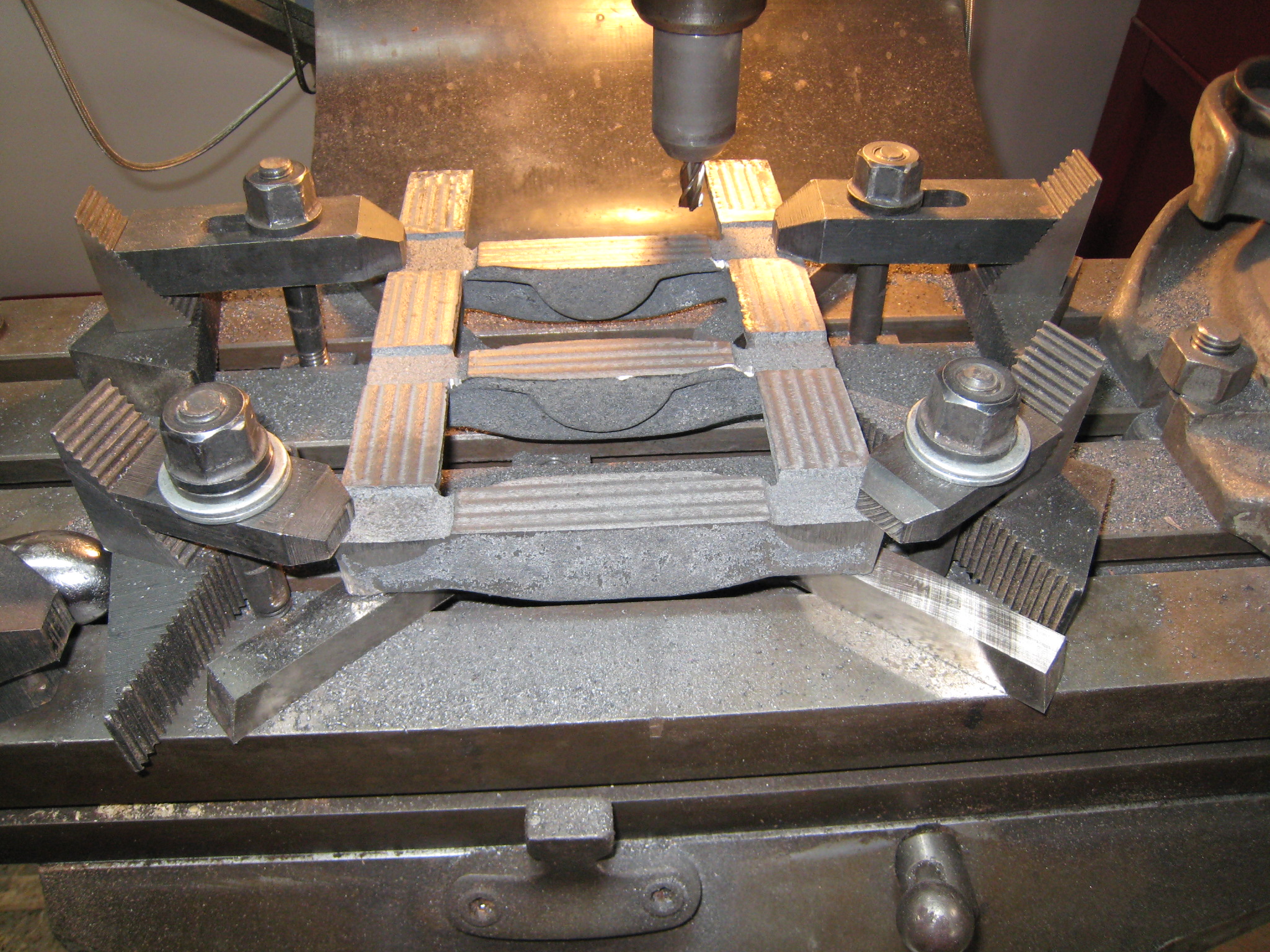
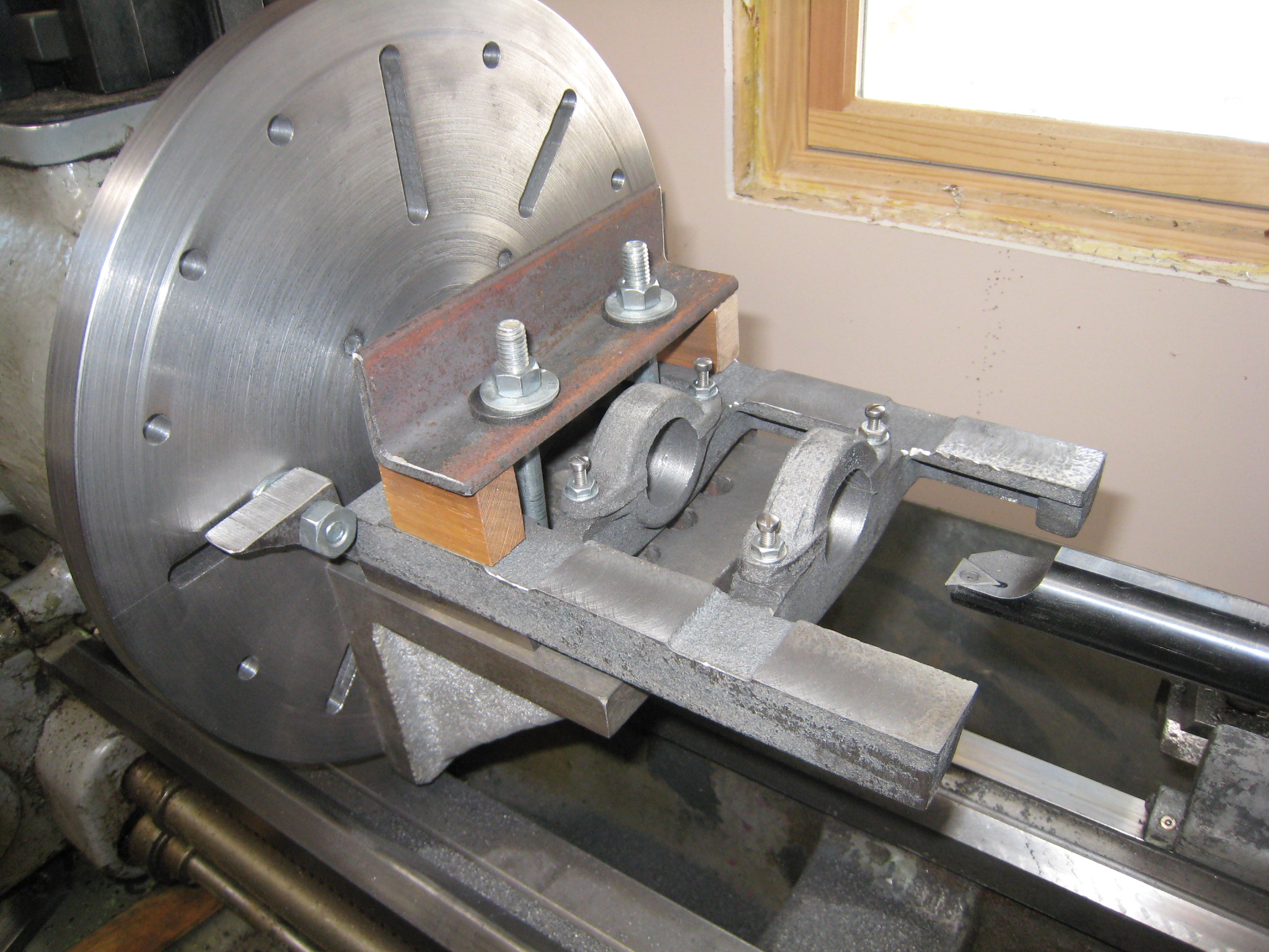
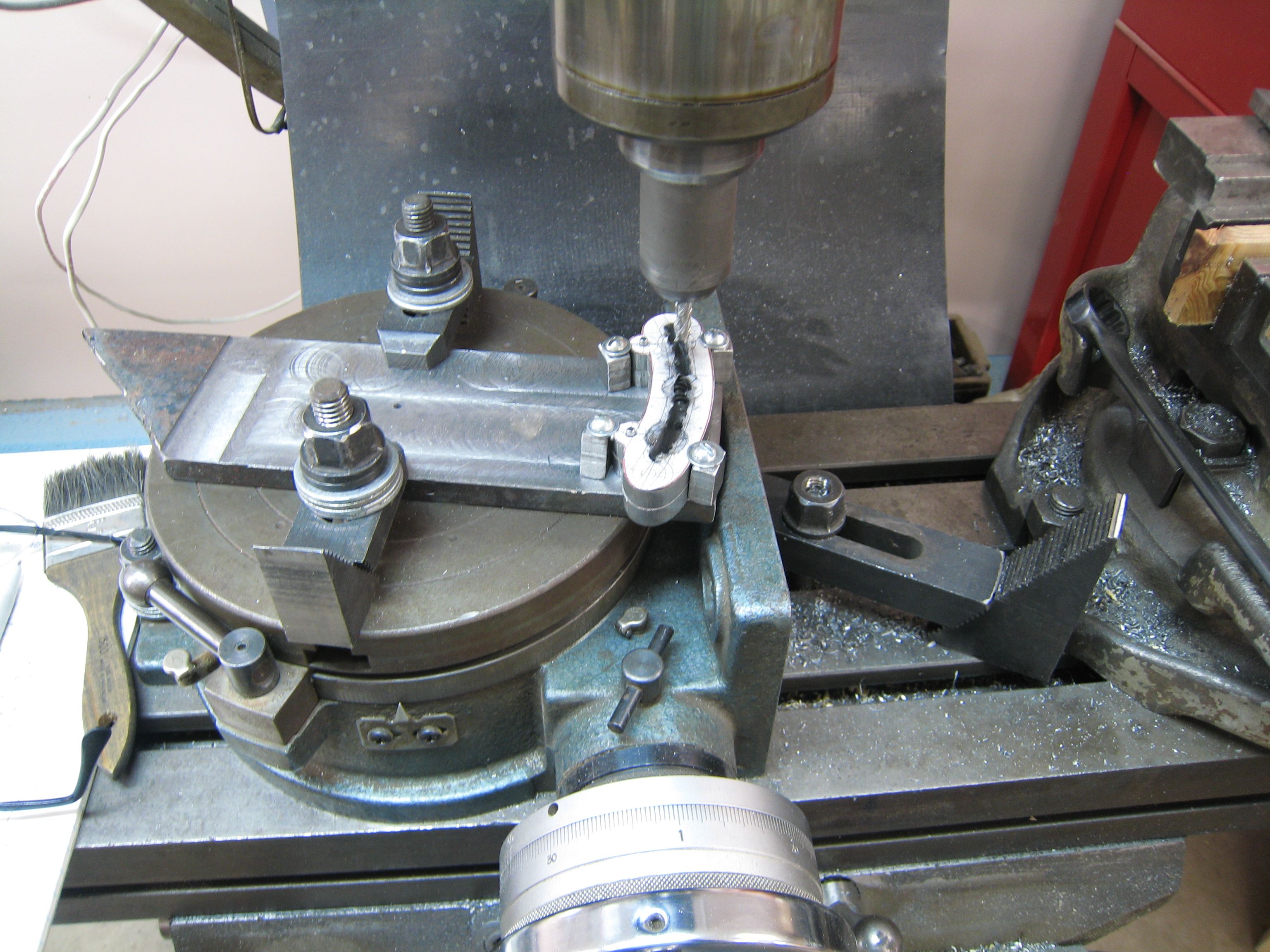
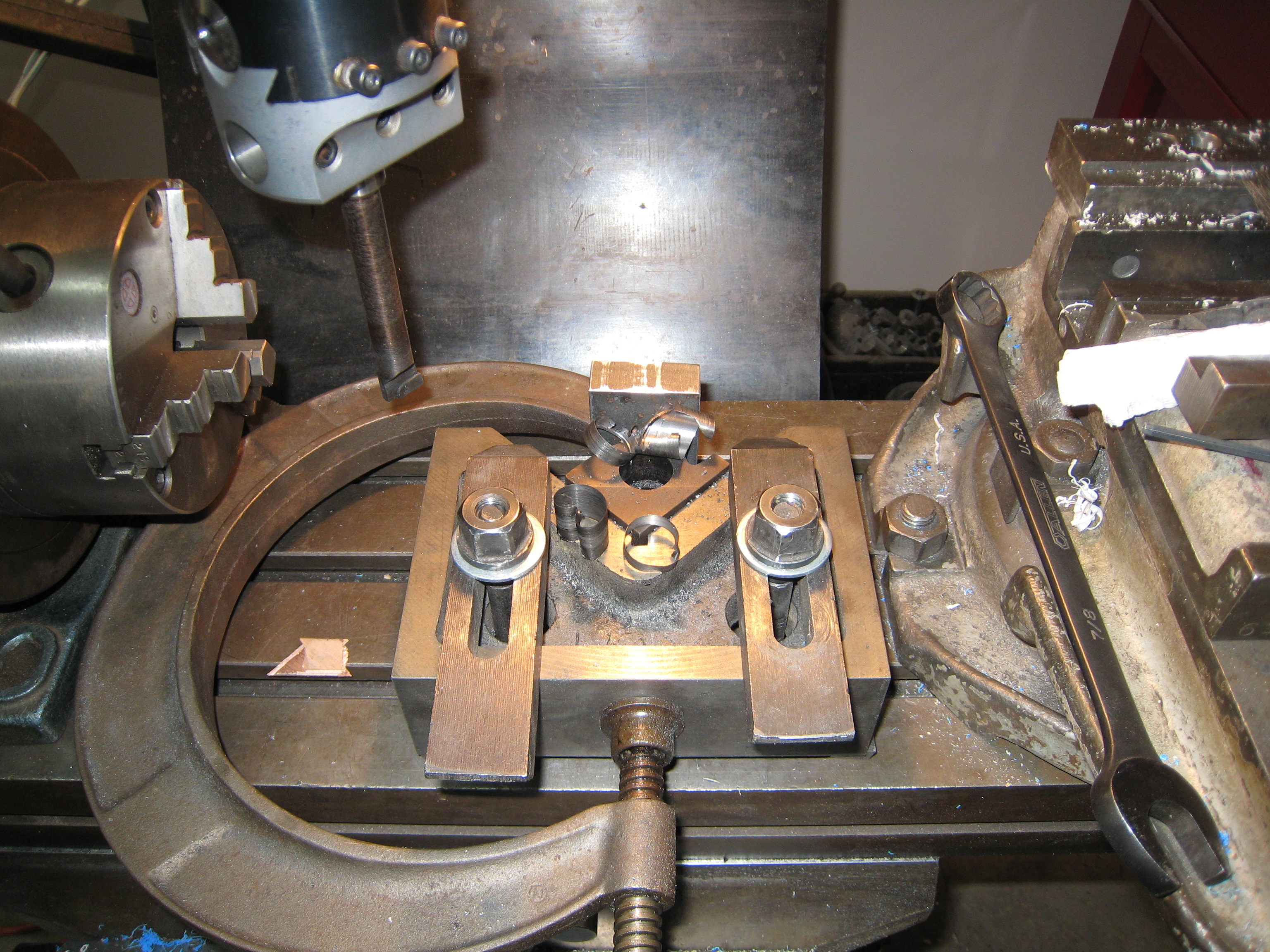
Four crankshaft Webs on rotary table (3/20/2008)
Crankshaft
The crankshaft is the part that takes the power out of the engine. There are torsionl forces that must be transferred. An accurate fit of this built up crankshaft is needed for good long term service.
The webs are first rough cut from 3/8" mild steel.
Then a rotary table was used to machine all the webs at the same time (see picture above).
A keyway was broached in both the main and journal holes.
The broaching was done on two webs at a time to assure alignment.
When the crankshaft was assembled, it had a slight wobble. Initially I thought that I had misaligned the webs, but I could not twist them a little and get the wobble to go away.
Wobbling Crankshaft Video: Watch the ends of the shaft. (4/12/2008)
The crank wobbled (see video)
After some investigation, I found that the error was in the sleeves that I made to go from the 1/2" shaft to the 15 mm ID of the bearings (6202 bearing). Drill bits really can wander quite a bit. I had used a center drill, 1/8", 1/4", 3/8", 31/64" and 1/2" reamer for the holes. The second set of sleeves were bores just before reaming. This yielded a much superior sleeve.
At this time I also switched from a 3/8" web to a 1/2" thick web.
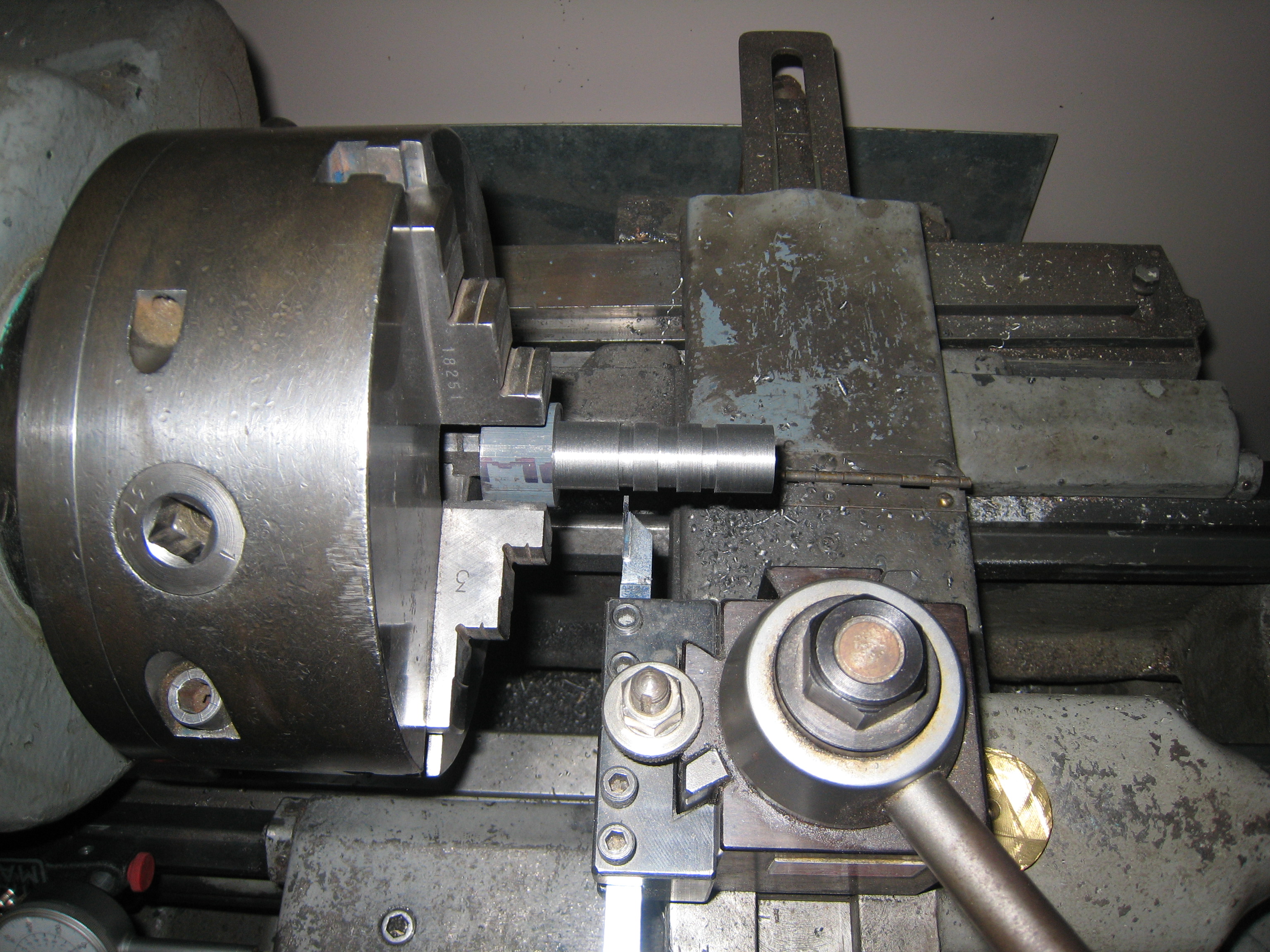
The Standards were honed next with a 6" long piece of Aluminum turned to a diameter of 1.365" OD. While turning the Standard at about 130 rpm in the lathe, I used the milling machine to move the home in and out of the standard at about 0.5 times per minute 2.5" stroke. I started with course grit (HC) and then used 320 grit (3-B) grinding compound. I used each grit for about 15 minutes. Although I could hear a slight grinding sound, I could see very little effect on either the cast iron or the Aluminum.
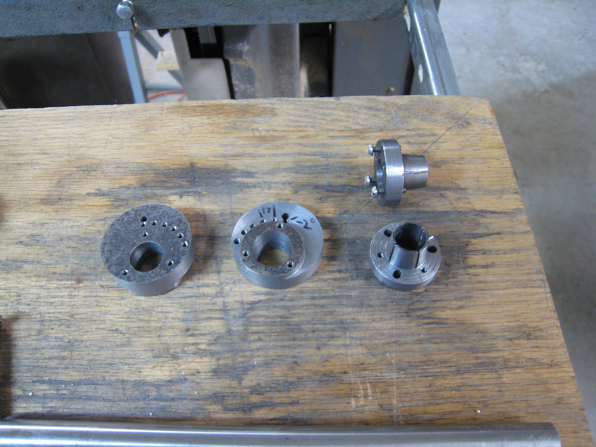
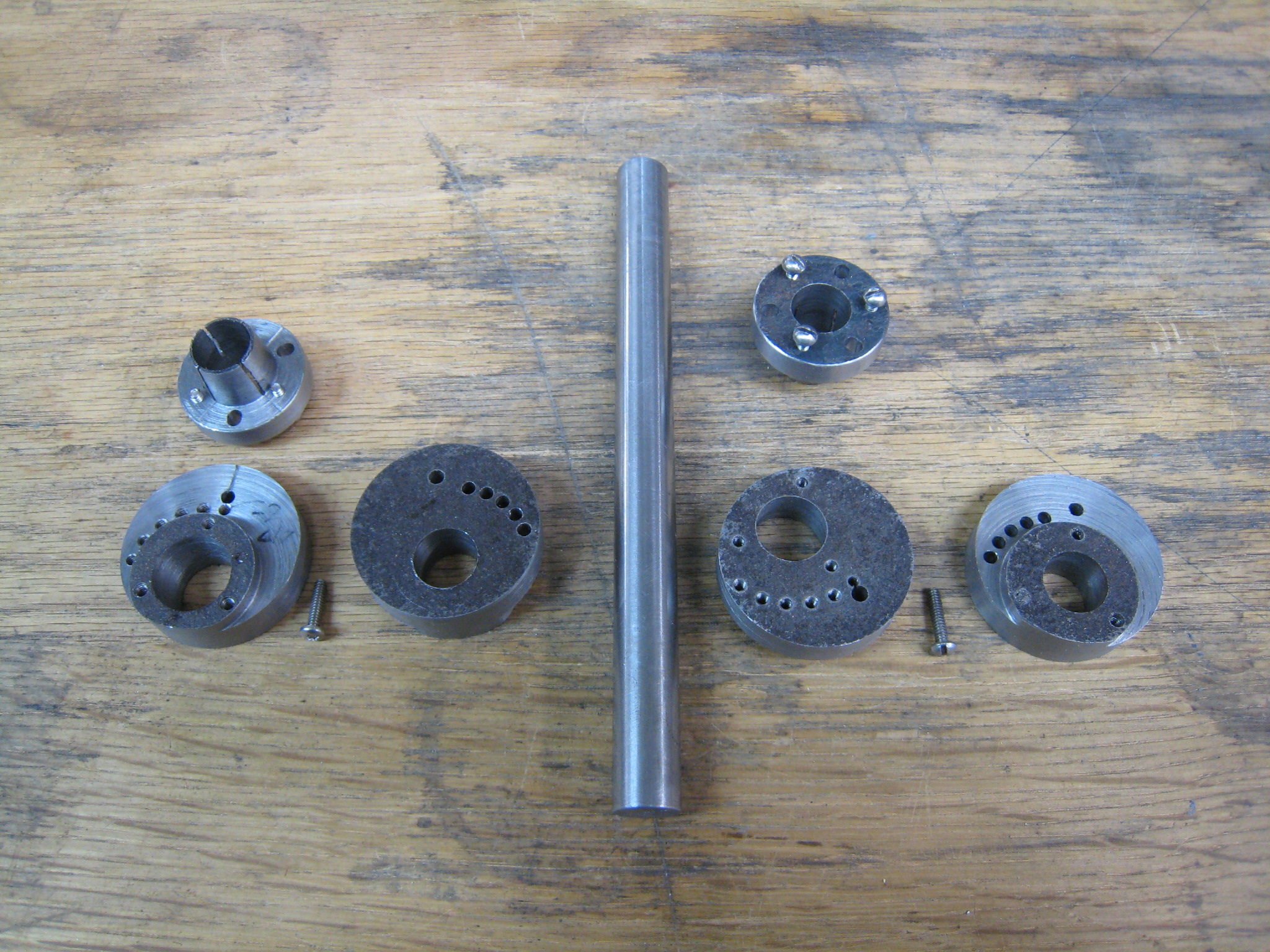
The stub and span between the legs of the standard were cut out next.
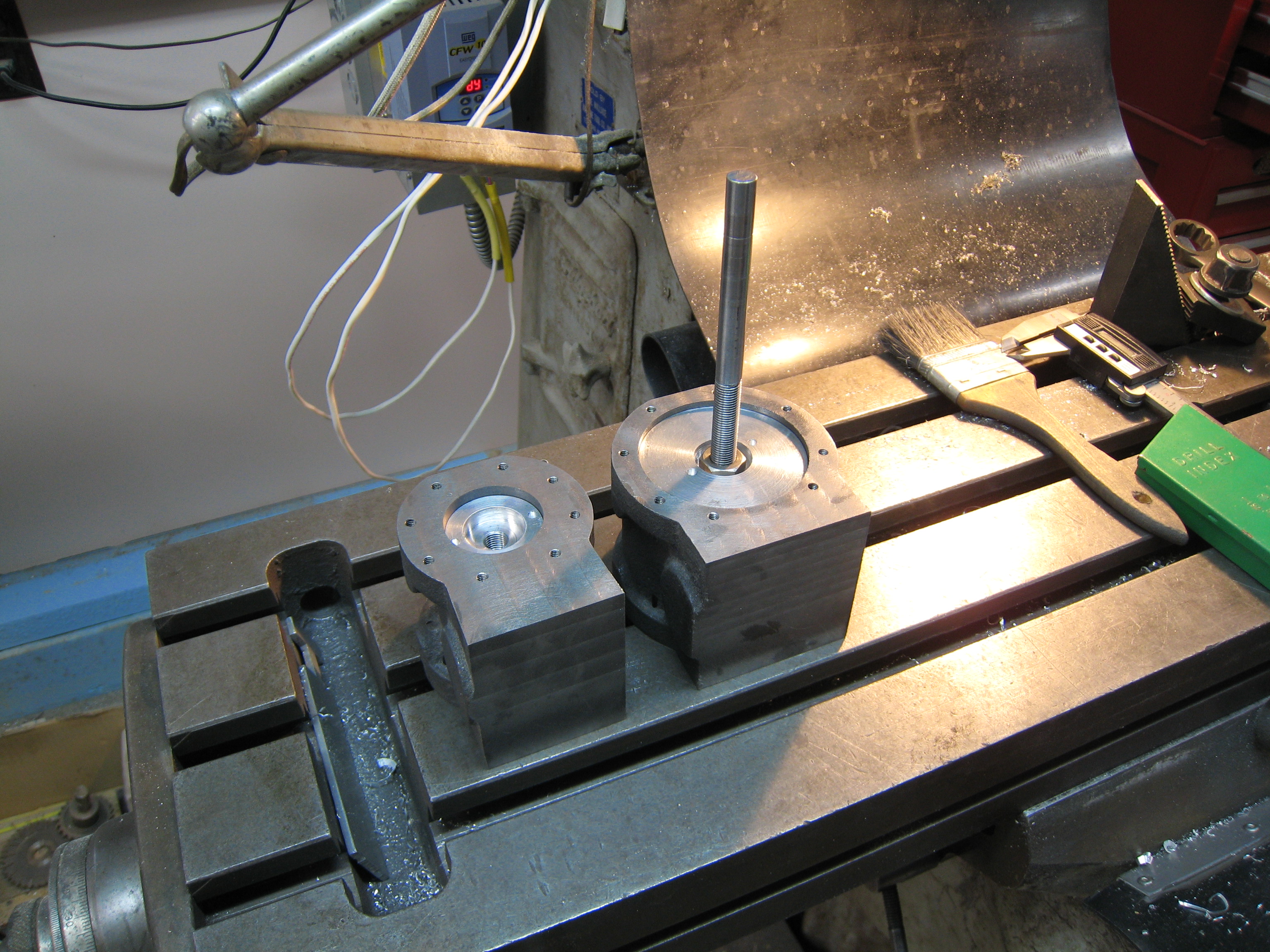
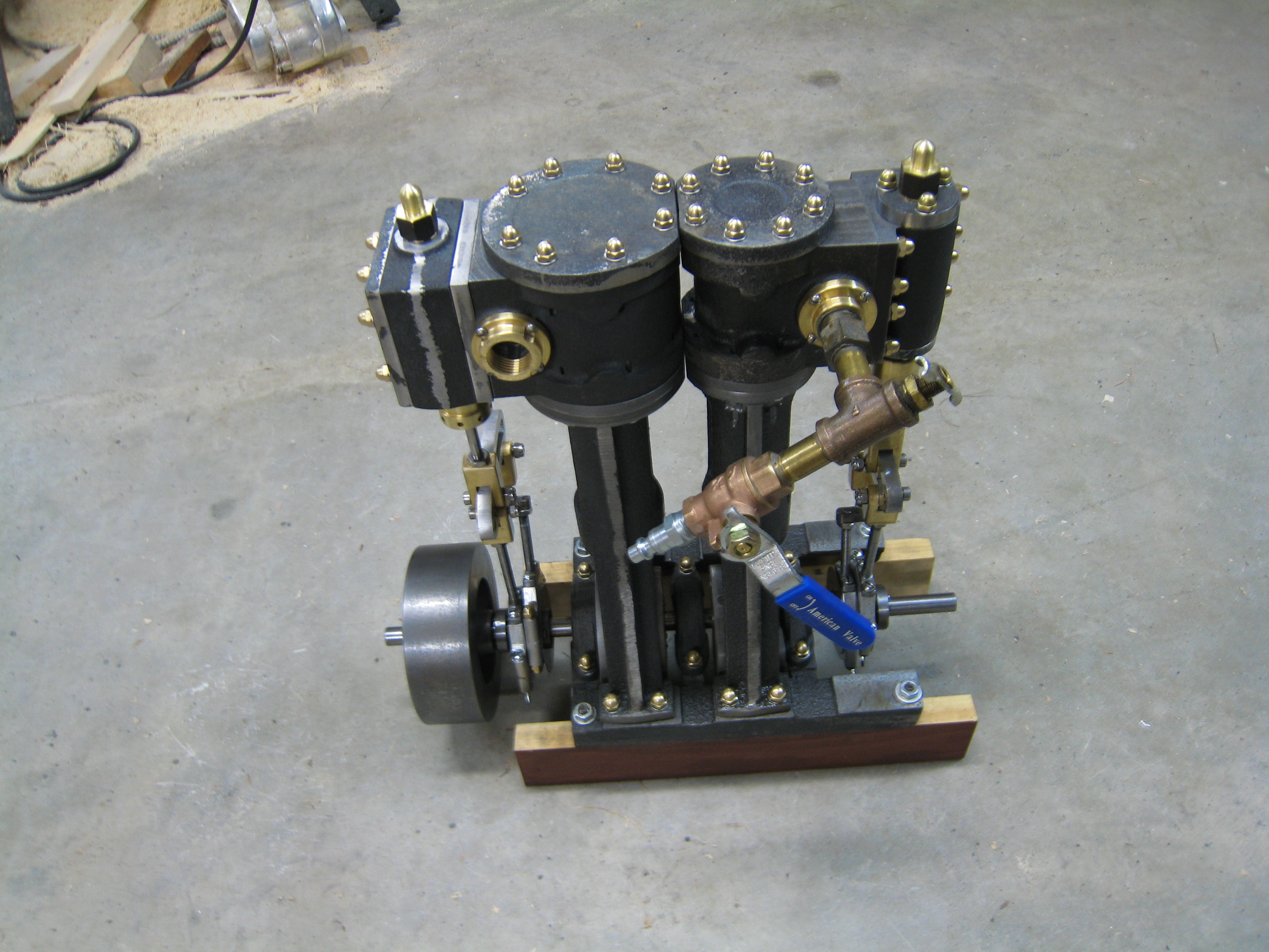
Profile of Base and Standard(5/3/2008)
End view of Base and Standard(5/3/2008)
You will notice that the lands on the base do not line up with the legs of the Standards. This is because I decided to not trim the HP and LP cylinders to make them sit as close together as possible. I stretched the crankshaft, but forgot to stretch the base. I will do a small amount of trimming of the Standard, Cylinder Bottom, Cylinder and Cylinder Top of both the HP and LP cylinders.
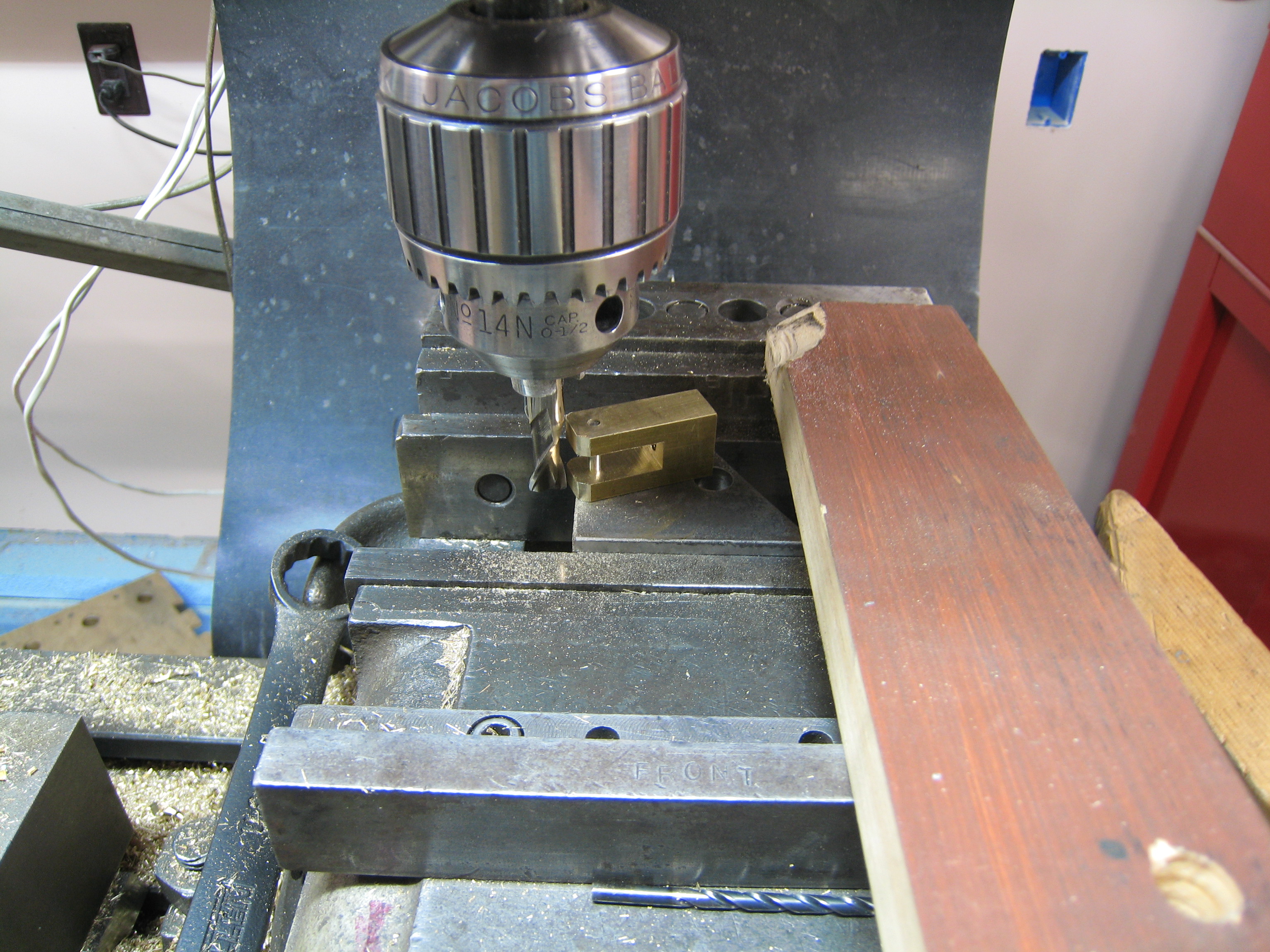
I have been busy with other matters so have taken only small amounts of time on the Crossheads.
First I turned down a 2" diameter Al rod to about 0.025
oversized (1.375+0.025) diameter. In the same setup, I drilled and tapped the 3/8"-24 piston rod hole.
Next I mounted the Crosshead on 2 V blocks and bored the bearing pockets. This was done by first drilling a 3/4" hole clear through the Crosshead. while still
mounted in the V blocks, I bored the top bearing pocket to the proper depth. To turn the Crosshead over and get accurate alignment I put the drill chuck back
in the milling head and used a tool made to be 3/4" dia on one and 1/2" dia on the other so that when mounted in the drill chuck, would give the proper
position and rotation to the Crosshead for re-clamping in the V blocks.
Once clamped, the second bearing pocket can be bored in the Crosshead.
(Sorry I did not take any pictures at this point. (9/08))
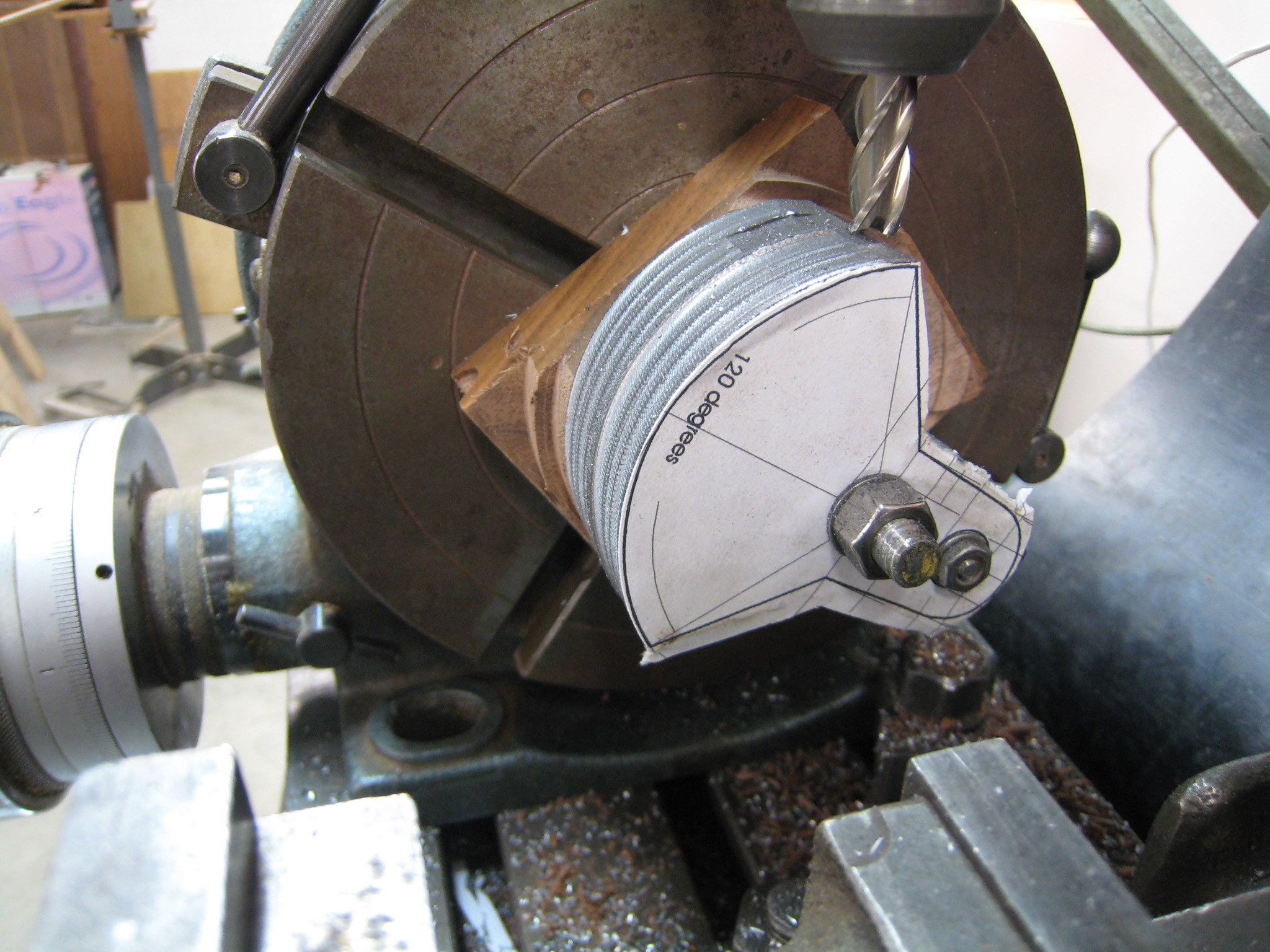
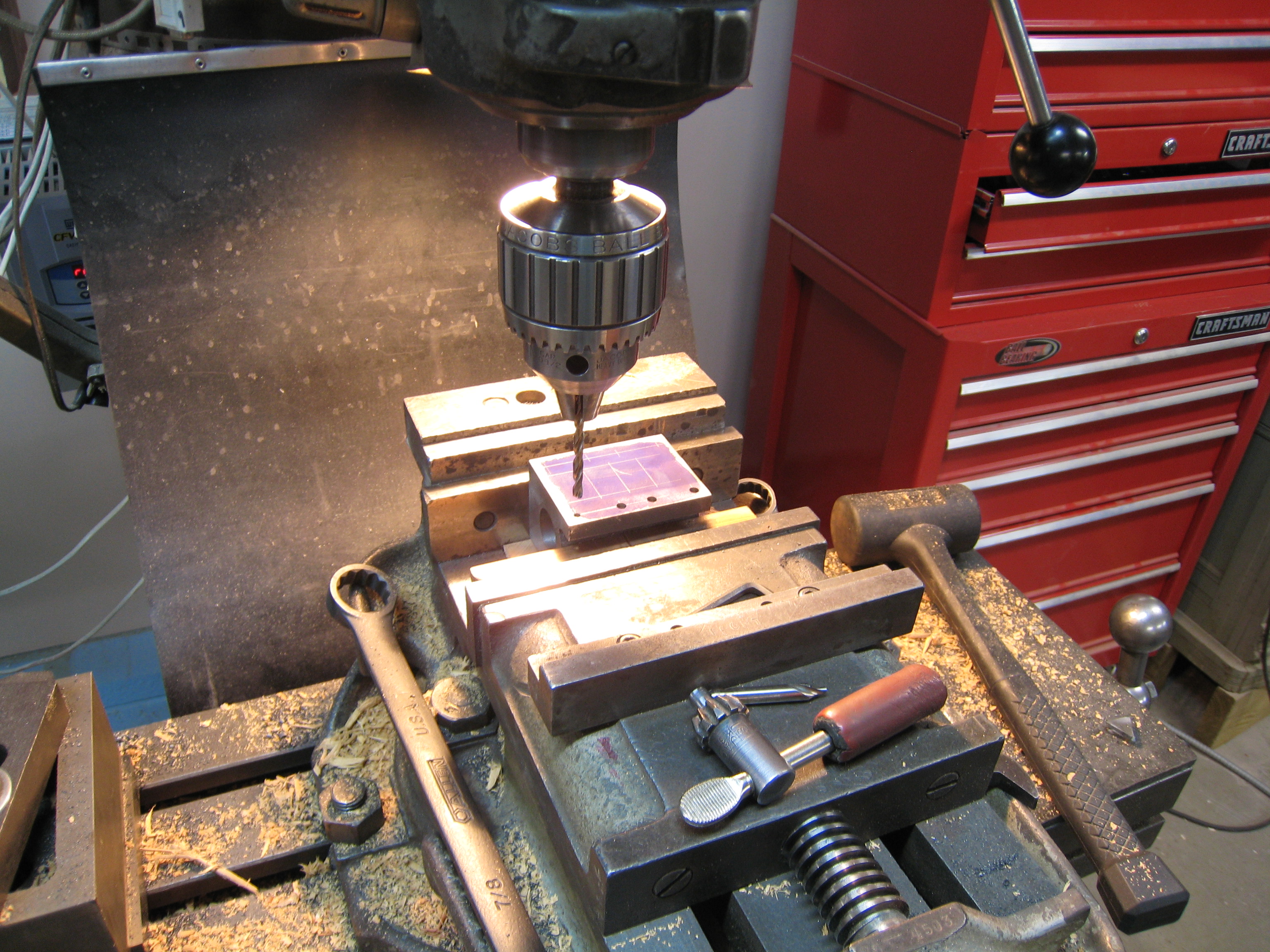
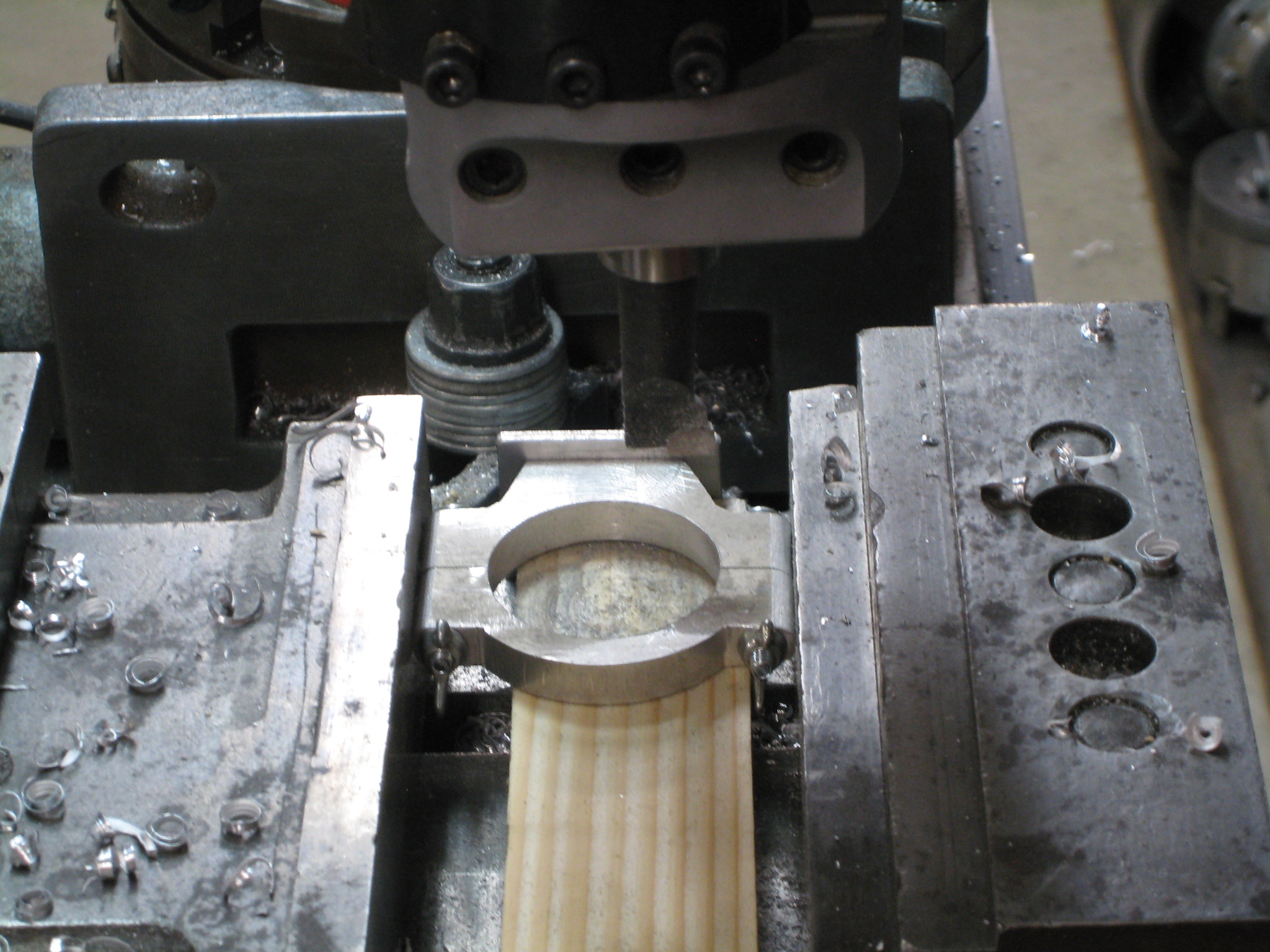
Opening up the bottom of the Crosshead for the Connecting Rod was accomplished with the use of a rotary table and a 3/16" dia end mill. Basically, the 3/4"
hole across the Crosshead is being opened at a 16 degree angle to a width of about 0.415".
The alignment and clamping of the Crosshead was accomplished by using a plug the diameter of the Crosshead bearing. This plug was threaded with 3/8"-16. A nut on a 3/8"-15 rod is
jammed between the Crosshead and the rotary table to clamp the Crosshead. A Morris Taper with a 3/8" hole in its center is in the center of the rotary table to provide alignment.
Milling the bottom of the Crosshead(10/8/08)
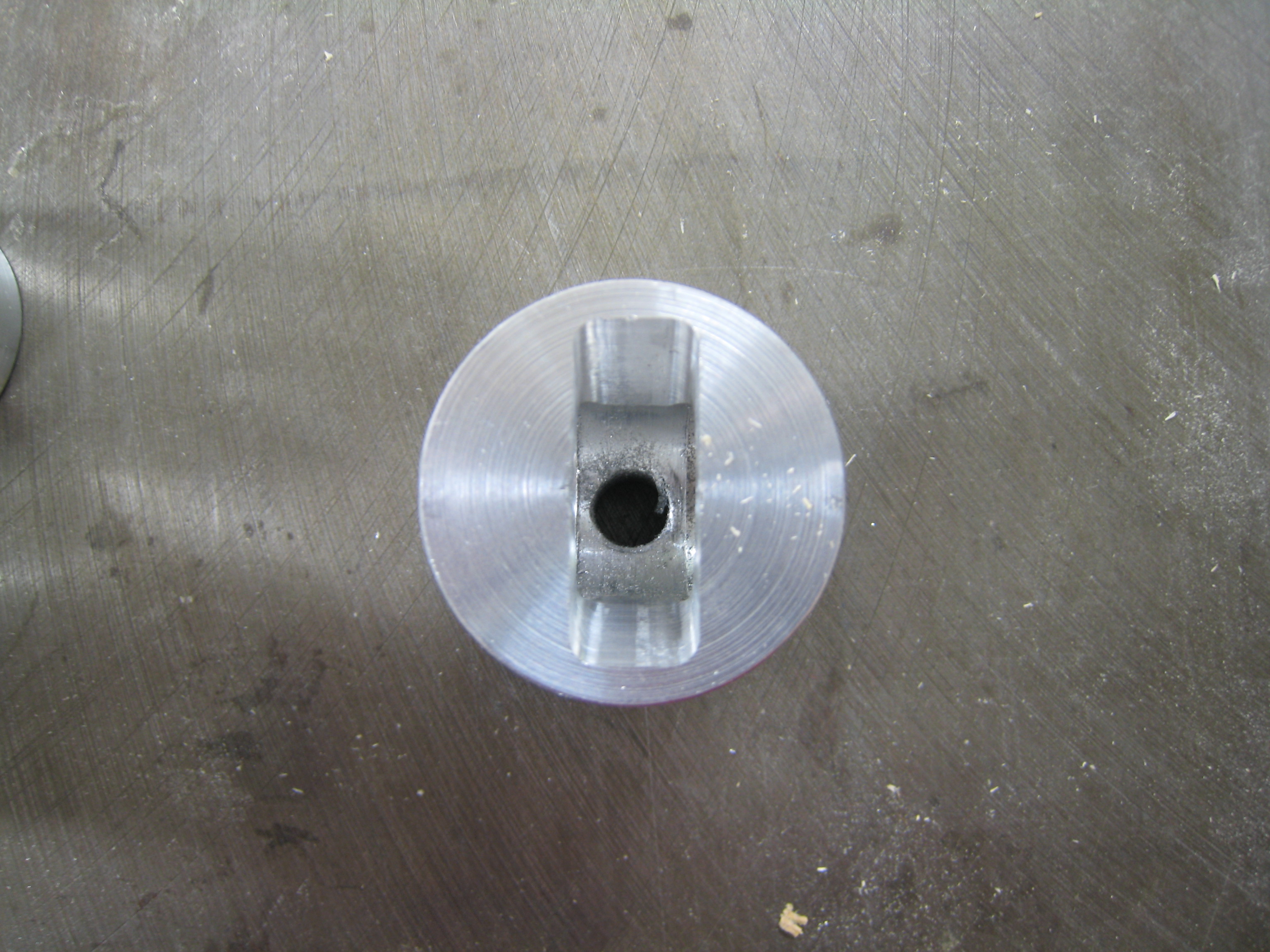
This is a view straight up the Crosshead(10/8/08)
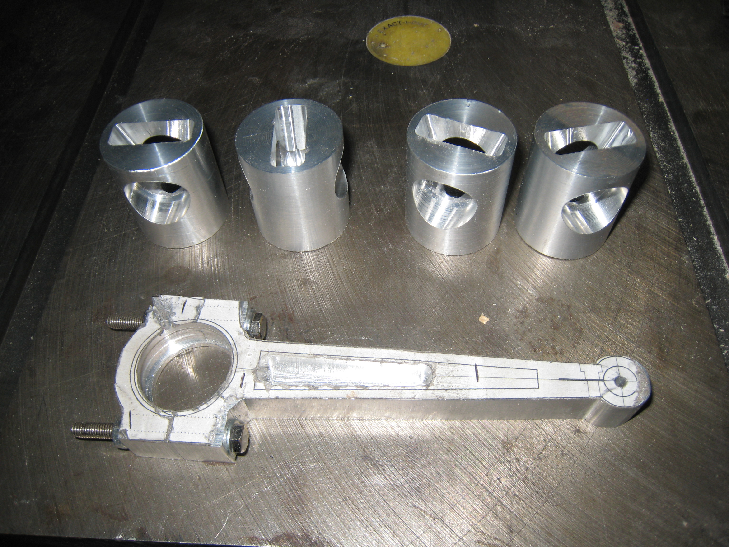
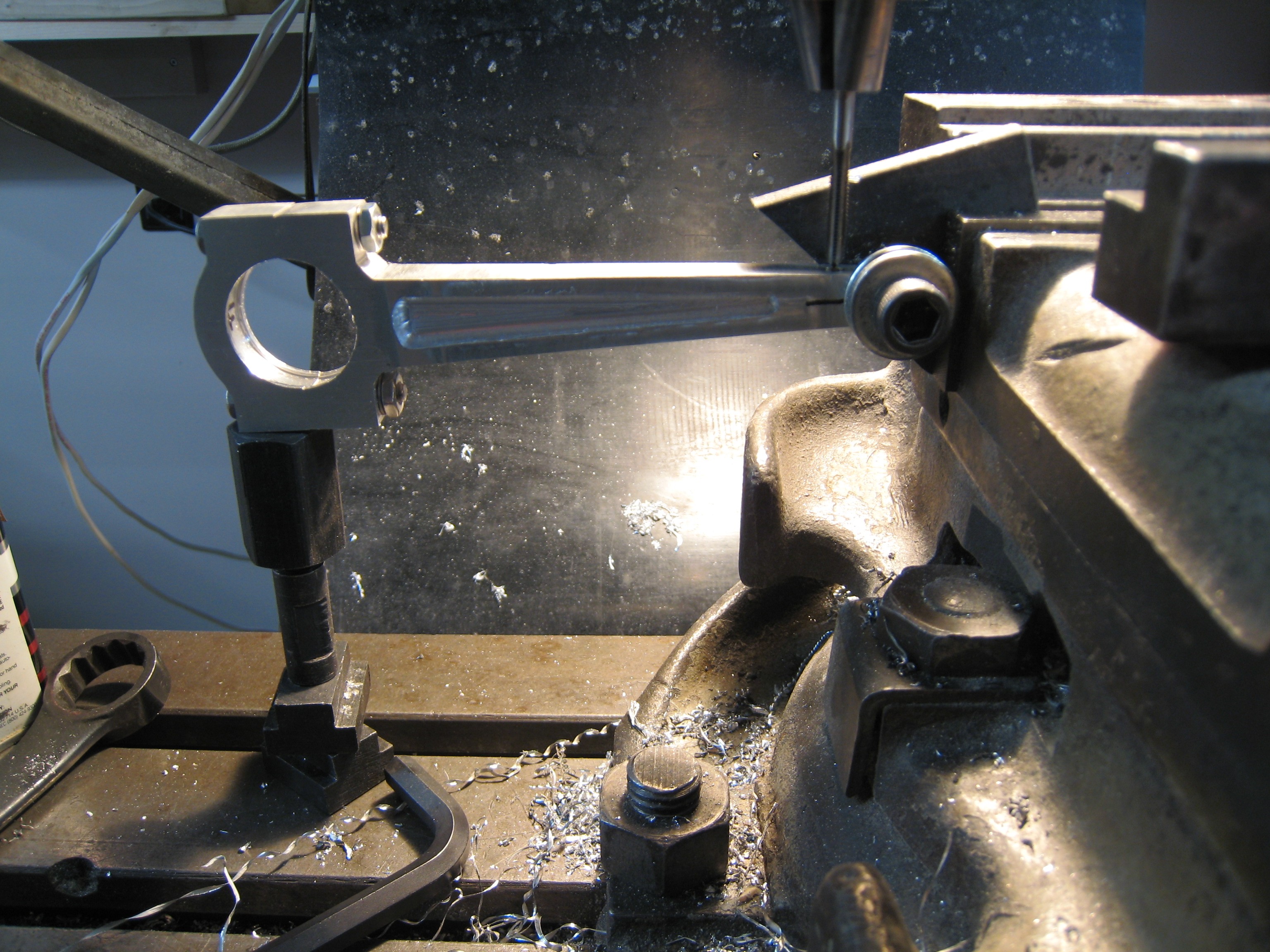
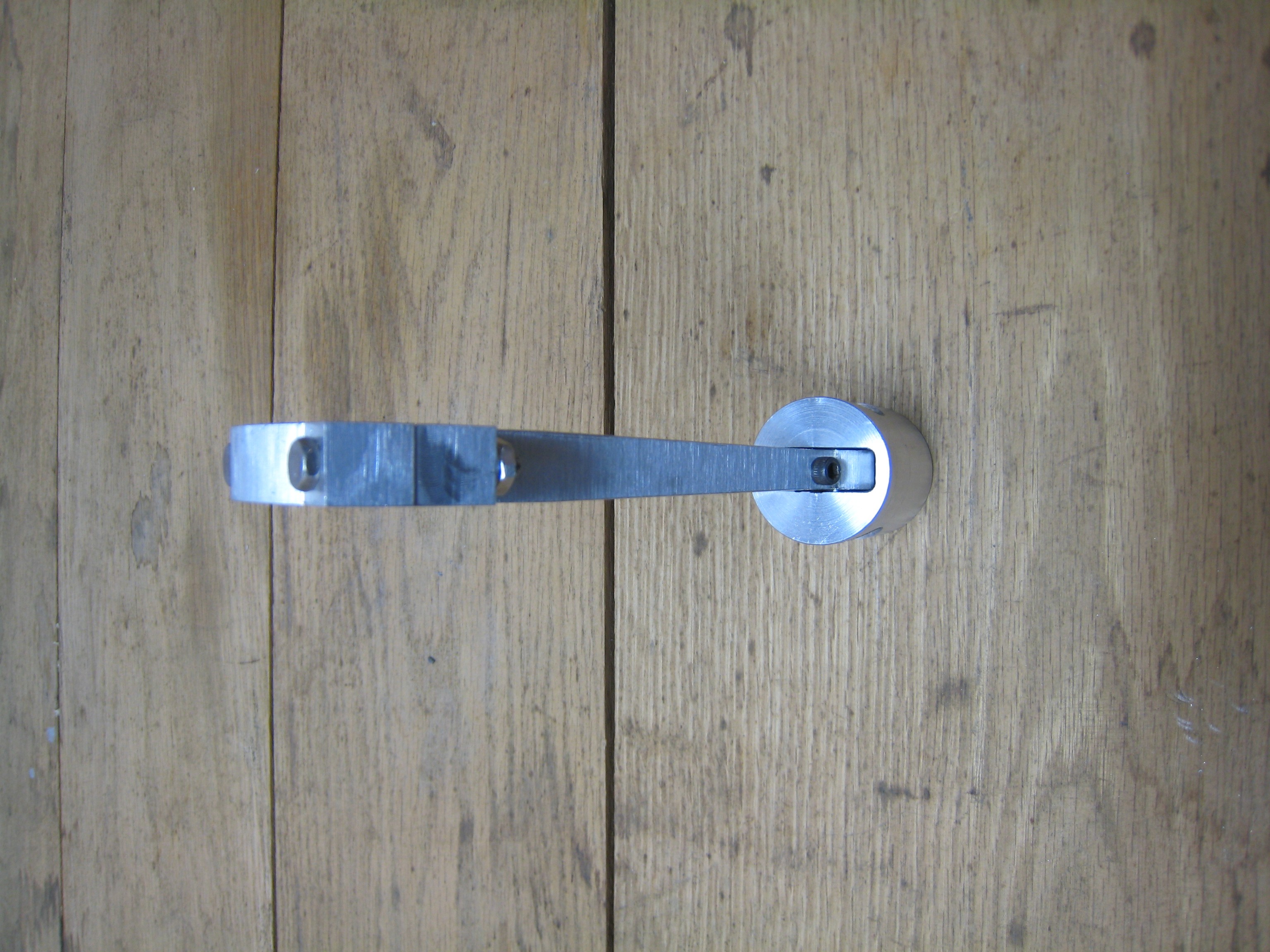
Here are 4 crossheads and a connecting rod(10/8/08)
TEXT needed
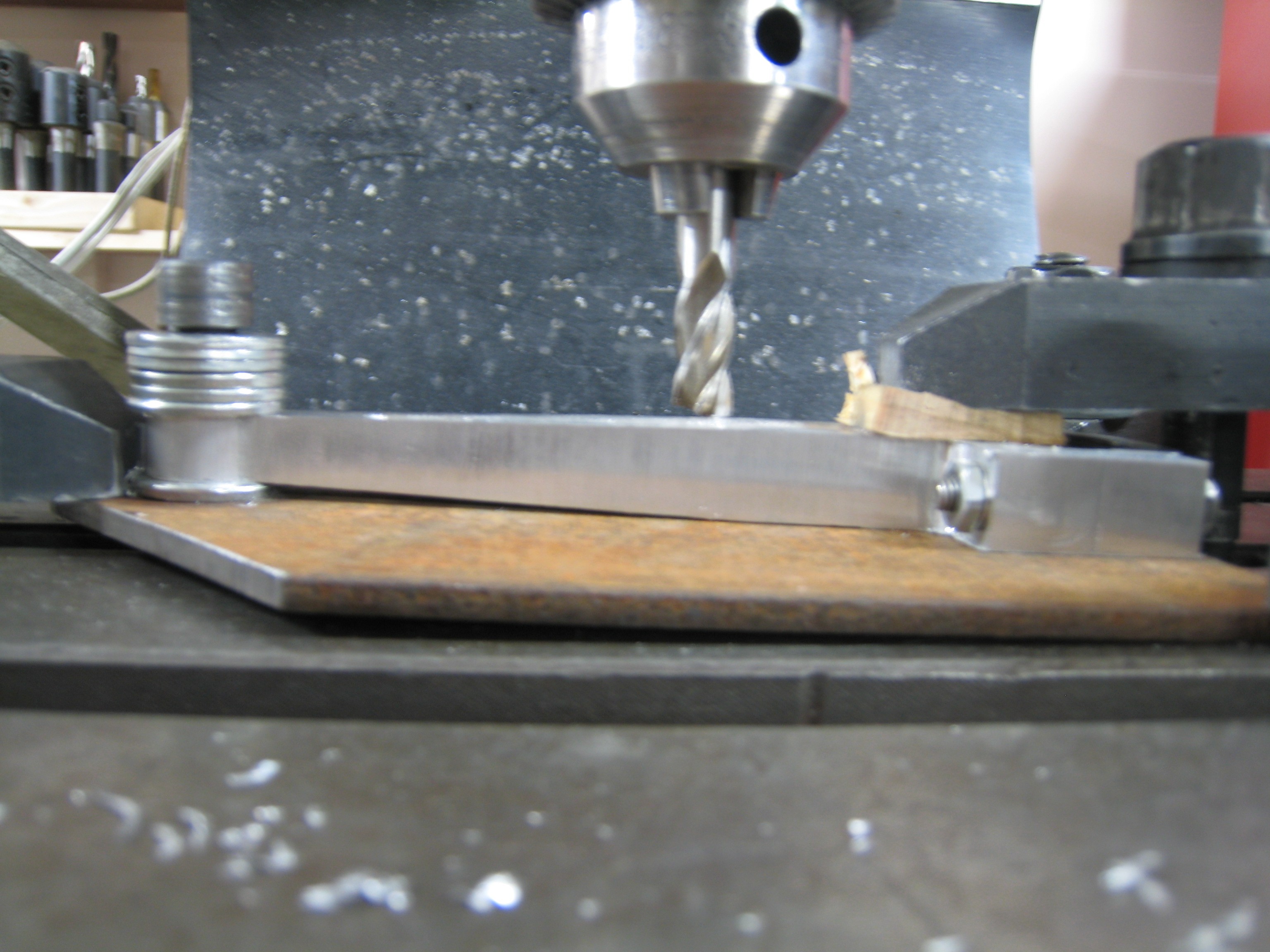
Milling the taper on the connecting rod(10/31/08)
Threading the crosshead clamp on the connecting rod (10/31/08)
Here are 4 crossheads and a connecting rod(10/31/08)
My second crankshaft was made with 1/2" webs.
I also used a single shaft with cutouts for the big end of the connecting rod bearings.
This turned out to make for very good alignment in the main shaft.
I then proceeded to use cylindrical Loctite and thread locker Loctite assembling the crank shaft and bearings.
All looked great!
A problem arose when I started assembling the Connecting Rods, Crosshead and Standard.
The Standard started tipping toward the front and back of the engine a small amount.
It was enough that holding down the Standards would not permit the crank to turn with moderate force.
The Standard had its largest deflection when the crank was at 90 degrees to top dead center.
I took the Crankshaft apart without heating without much trouble and investigated the cause.
Somehow the two holes in the web were not parallel.
Since I drilled all 4 webs at the same time, I was surprised to see this difference.
Dean Merrill suggested that I bore the holes, that drills can wonder significantly.
(For those of you that are counting, this is the second that drill bit wondering has caught me.)
My third attempt at the Crankshaft was made with new webs and the previous shafts.
The first Standard worked very well.
I then located the standard attachment holes in the base, tapped them for 10-24 and all was good.
The second Standard had a wobble.
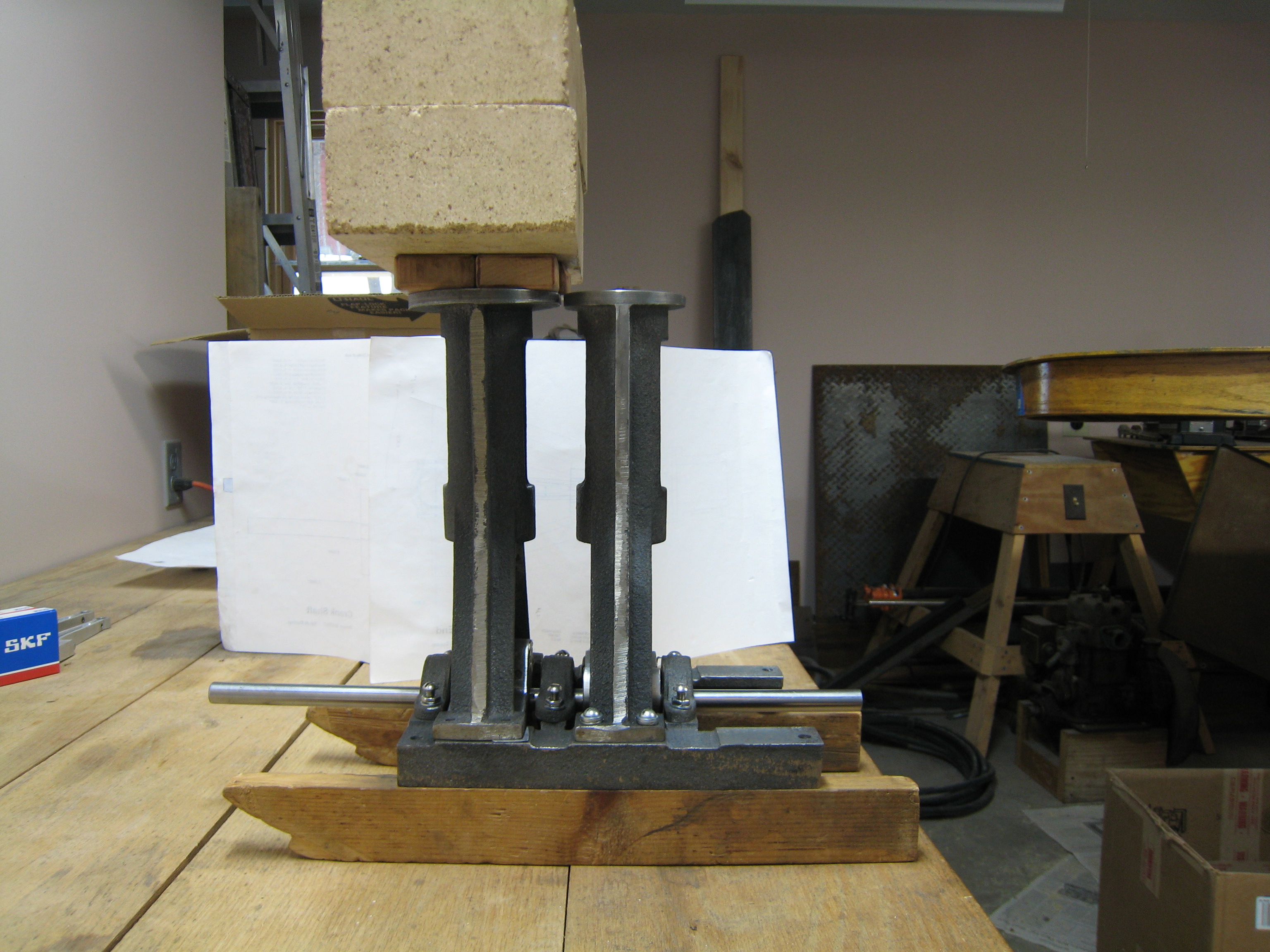
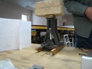
After some frustration trying to determine the cause, I put 3 bricks on top of the Standard to keep it from moving around.
I found the problem was at the top and/or bottom of the stroke.
Looking a little more at the setup, I found that a 0.003 shim under the front side of the two legs let the Crankshaft turn fairly freely.
This was a surprise to me as I had turned the Standard feet, bore and top in one setup.
The next day when I resigned myself to bolt down the LP Standard with a shim, I found that I did not need the shim. I do not understand what changed because the Crankshaft remained bolted in place.
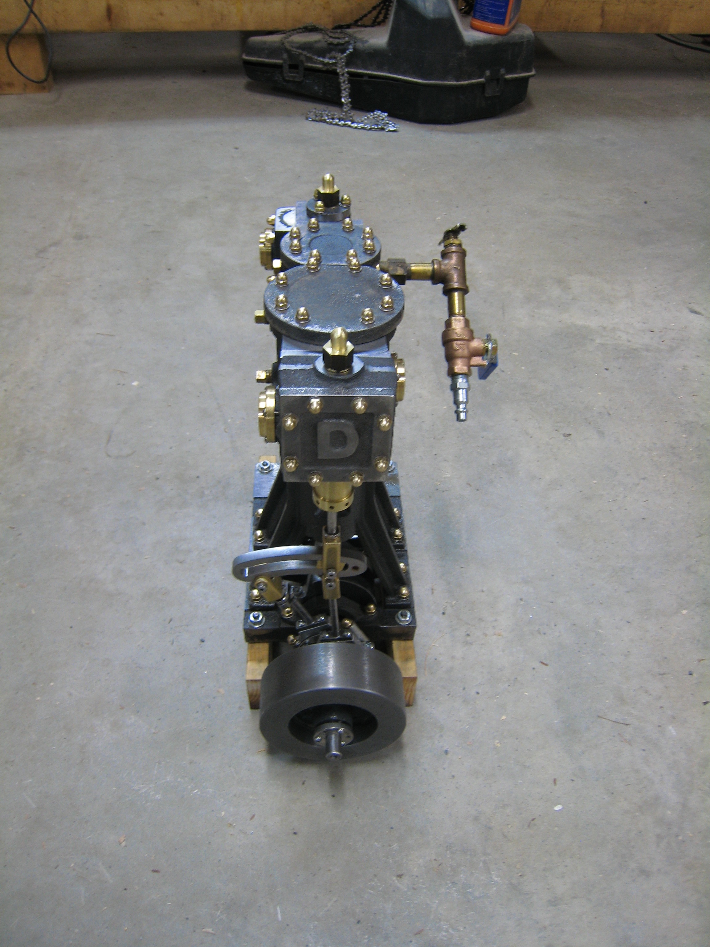
HP Standard mounted, LP Standard being aligned (1/1/09)
Movie of the mounting of the LP Standard (1/7/09)
Two www.youtube.com videos of the LP standard alignment.
It was amazing to me how long it can take to drill and tap the 16 holes on the top and bottom of the 2 Cylinders.
There were also 48 holes to drill on the Cylinder tops, Cylinder bottoms and top of the Standards.
The holes on the HP Cylinder are symiteric. Note, on the LP Cylinder, the holes are not symmetric in both dimensions.
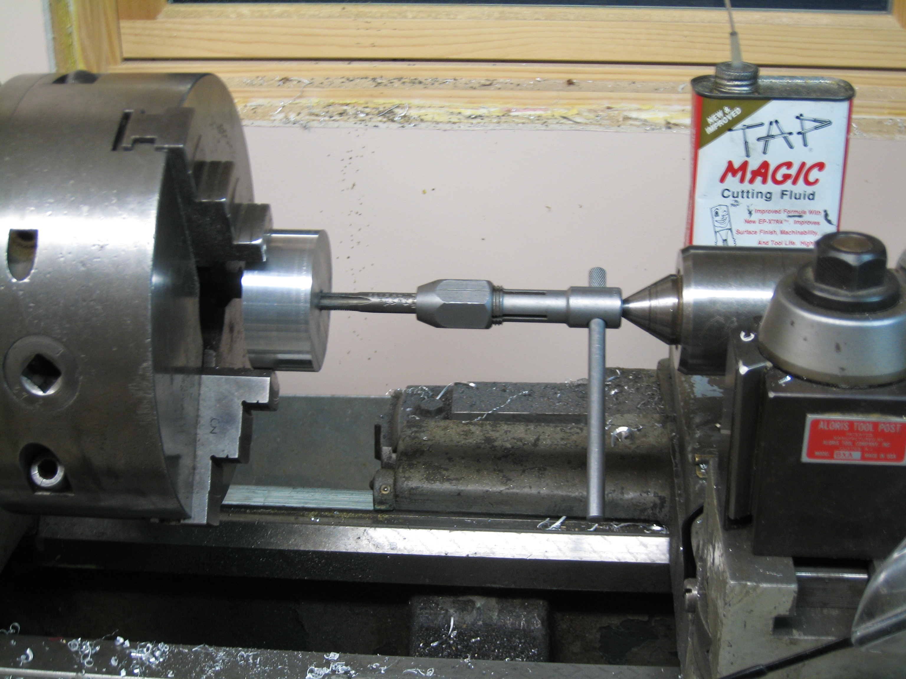
Boring the HP cylinder with a 1" boring bar (1/9/09)
Honing the HP Cylinder (1/10/09)
Hone movement from the Mill to the Lathe (1/10/09)
Hone movement from the Mill to the Lathe (1/10/09)
Hone movement video
Facing the bottom of the HP cylinder (1/11/09)
Drilling the holes in the bottom of the HP cylinder bottom (1/11/09)
Boring the LP cylinder (1/12/09)
Facing the side of the LP cylinder (1/27/09)
Aluminum for the HP and LP pistons (1/28/09)
HP piston with groves for the rings (1/28/09)
Tapping the LP piston (1/28/09)
LP piston with groves for the rings (1/28/09)
Pistons and Cylinders (1/28/09)
Assembly of Base, Crankshaft, Standards, Connecting Rod and Crossheads (1/30/09)
The walls of the HP Standard was a little too big for insertion of the screws (1/30/09)
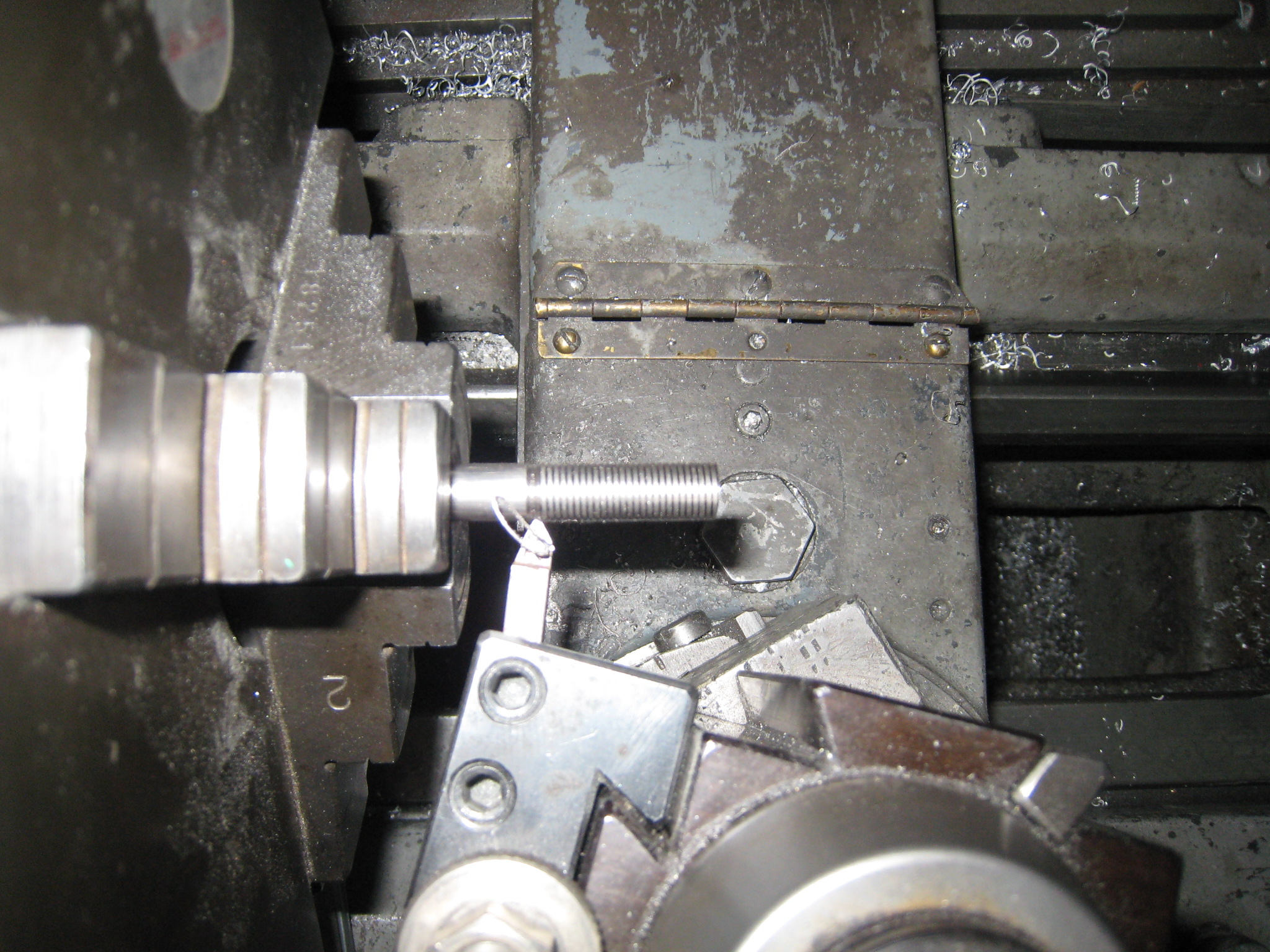
Threading the piston rod (1/28/09)
Broken carbide threading tool (2/1/09)
Lining up for drilling the HP cylinder ports (2/5/09)
Lining up for drilling the HP cylinder ports (2/5/09)
Boring the HP cylinder ports (2/5/09)
Port in the bottom of the HP cylinder (2/5/09)
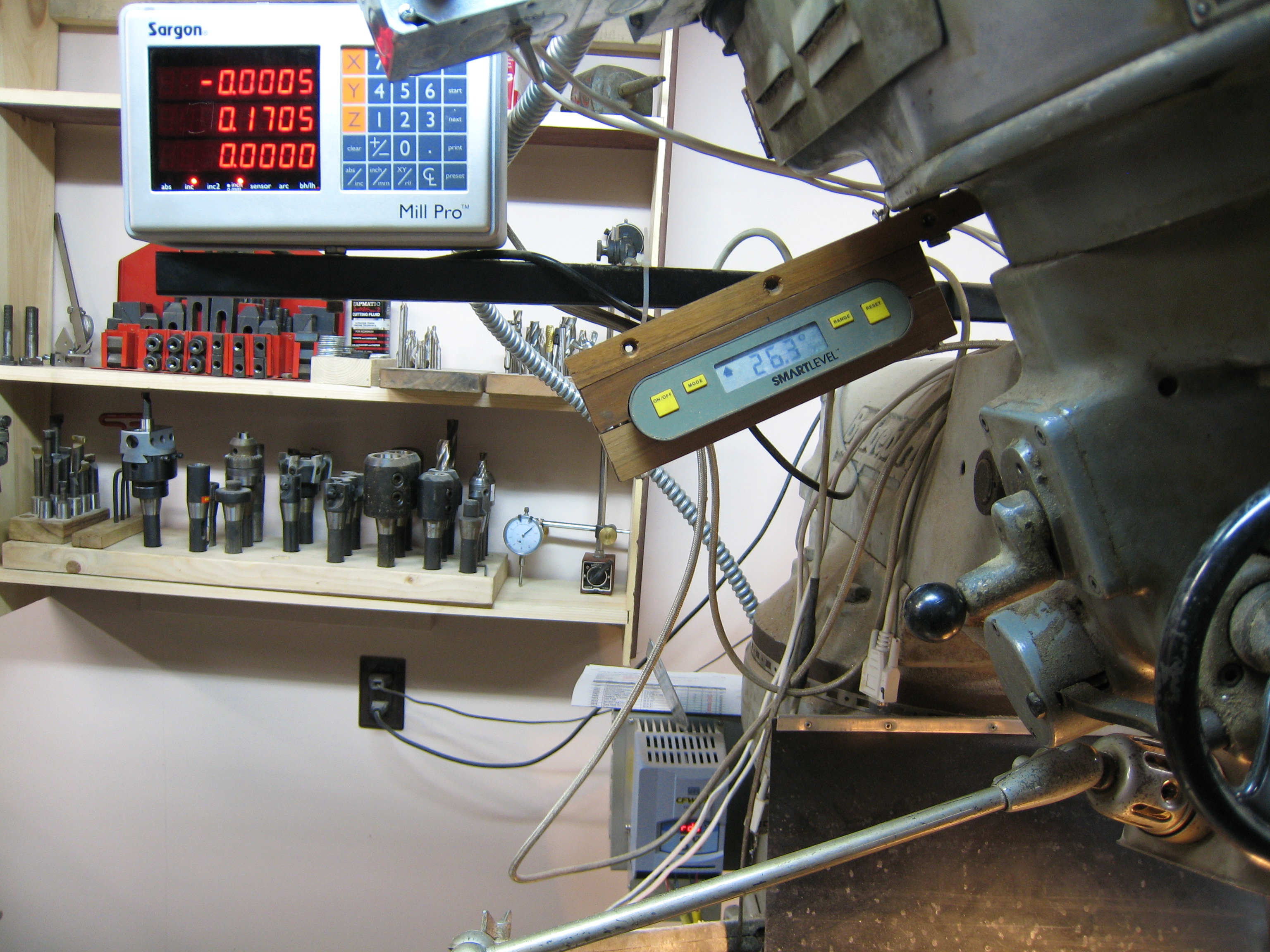
Angle indicator (2/5/09)
Lining up to 0.100 behind the false valve face (2/24/09)
Lining up to 0.100 behind the false valve face (2/24/09)
HP cylinder port (2/24/09)
LP cylinder port (2/24/09)
LP exhaust port (2/24/09)
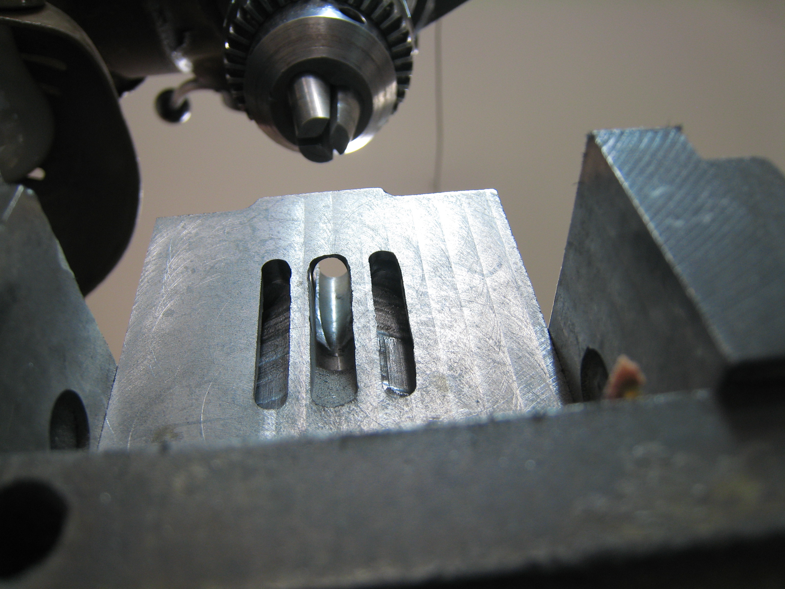
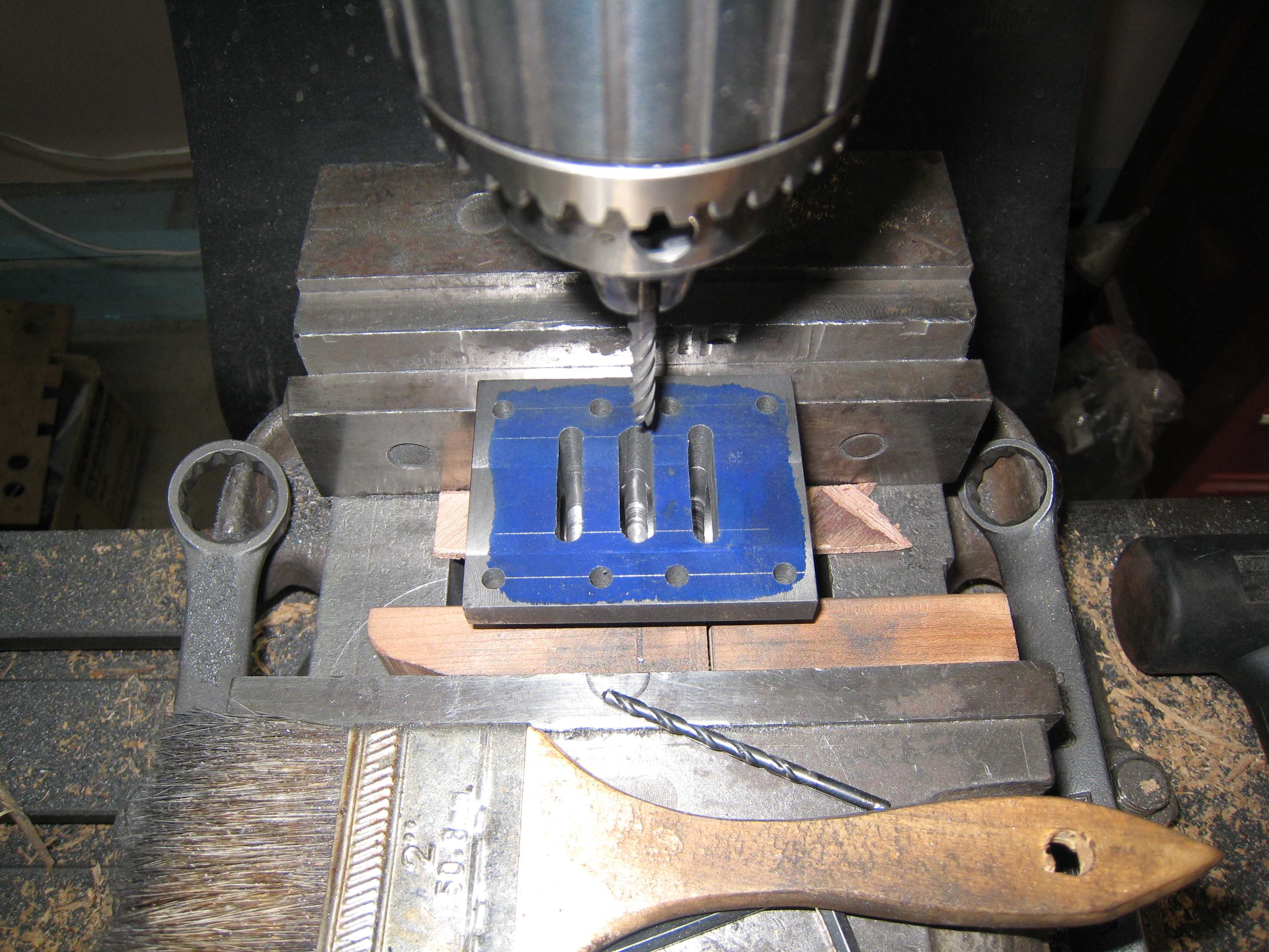
Stephenson Link 1/4" slot (4/14/09)
Stephenson Link slot: almost 3/8" (4/14/09)
After roughing out the first 1/4" of the slot in both Stephenson links, I widened each link to almost 3/8". After the second picture I used a 3/16" carbide end mill to make the last 0.005" pass on the two sides of the slot. The carbide end mill made a smoother surface than the HSS end mill.
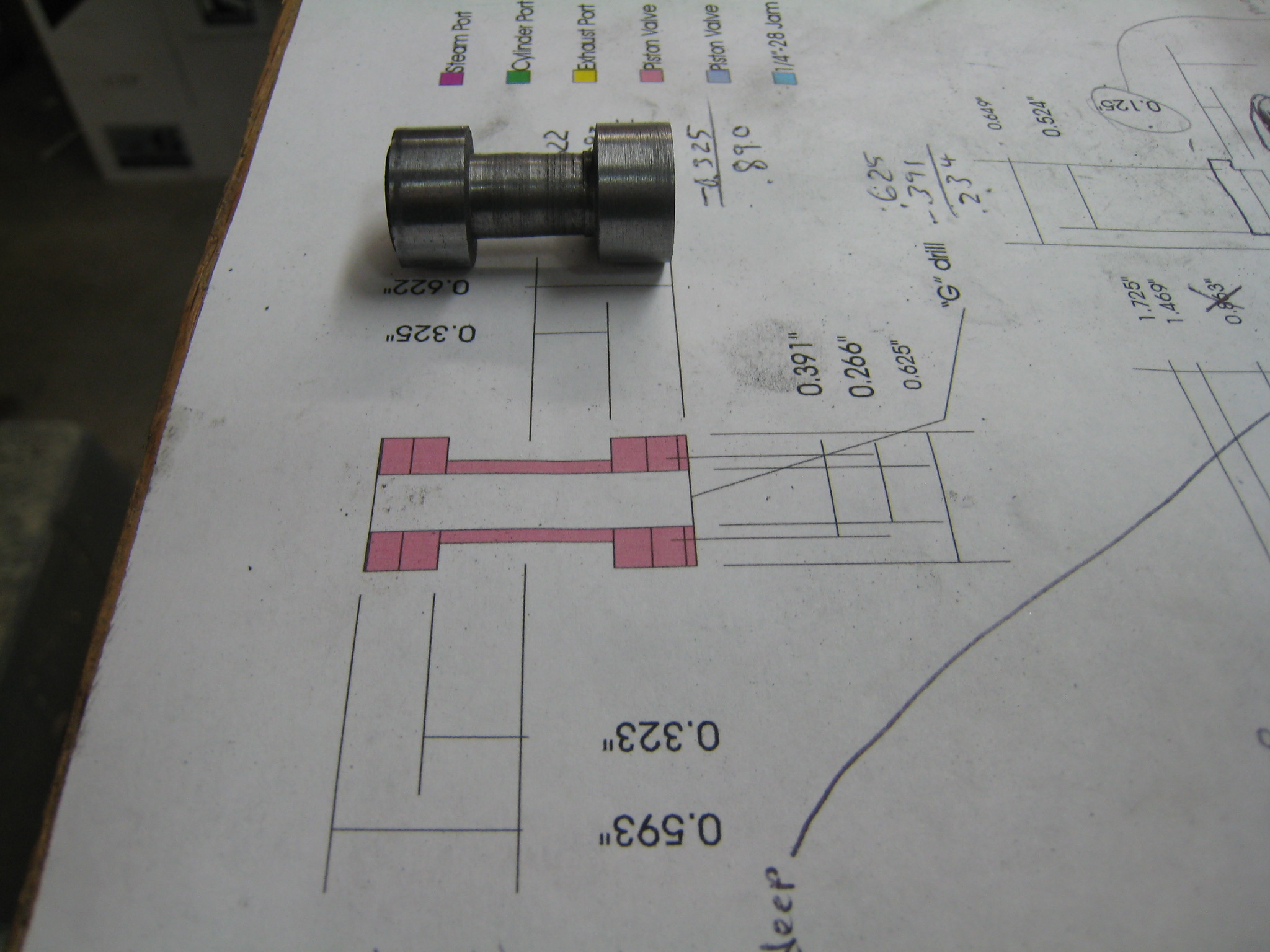
The Piston Valve Cylinder came next. It will have a 7/8" sleeve (I made the bore 0.002" oversized which will need to be compensated with the sleeve being 0.878" OD.)
Boring the Piston Valve Cylinder (4/23/09)
Piston Valve Cylinder mounting holes (5/18/09)
Piston Valve Cylinder Ports (5/18/09)
Piston Valve Cylinder Bore Ports (5/18/09)
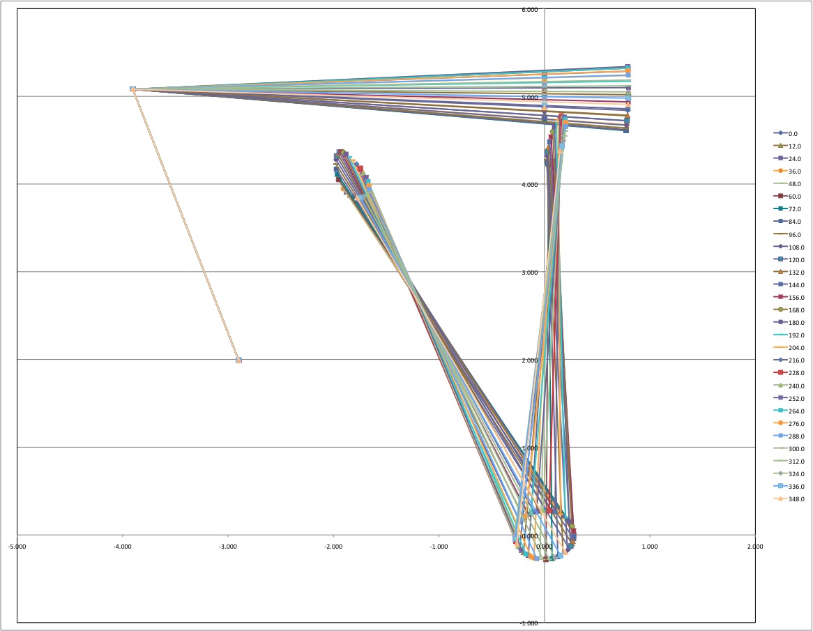
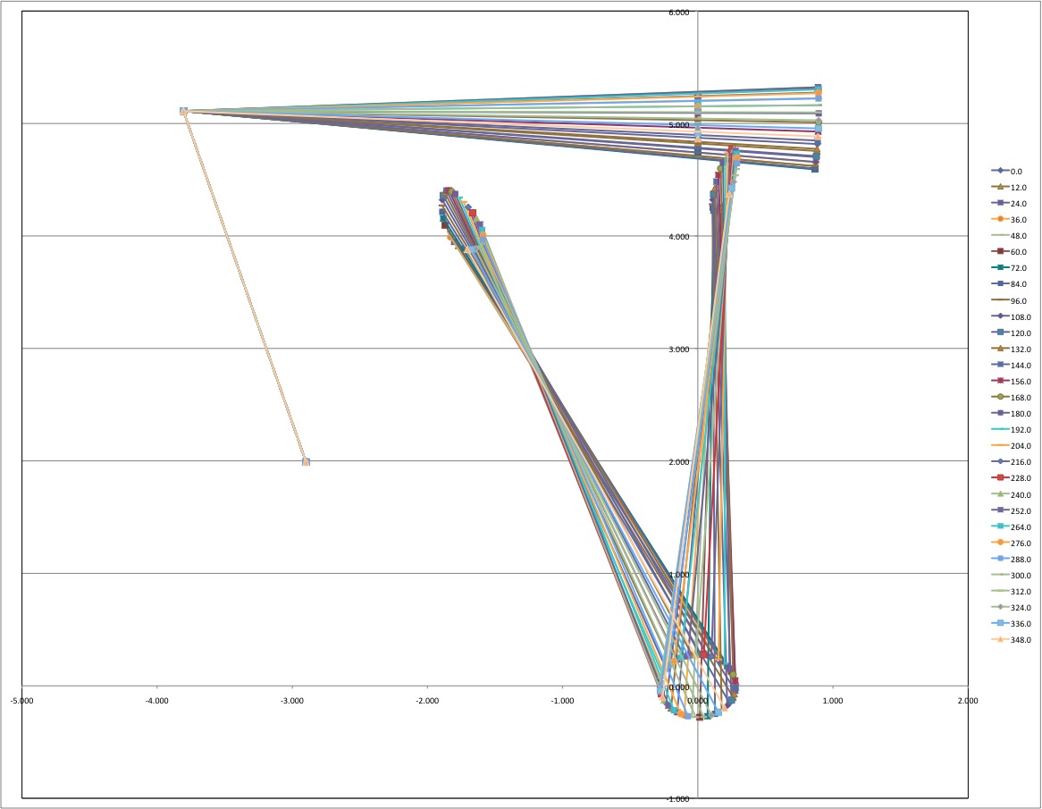
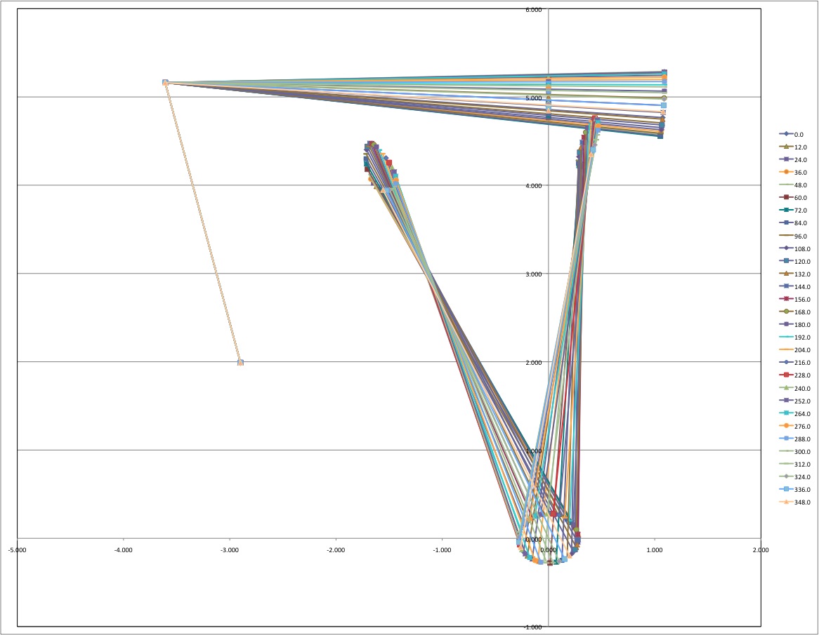
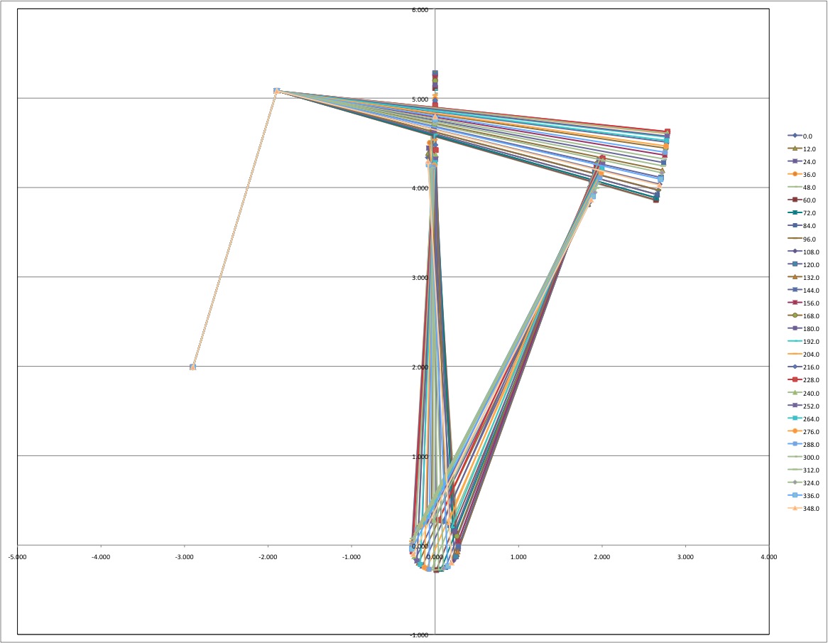
I spent some time modeling the Stephenson Link motion to minimise the slotting (motion between the link block and slot in the Stephenson Link. Conventional wisdom says that the horizontal (drag) link should be just that horizontal. For a marine engine, it also says that the drag link should be connected to the slot link as close to the forward valve connecting rod as possible and in the same arch as the slot. My modeling says that this connecting point should be horizontal to the valve rod pin (slightly higher than the arch. I calculated the locations of the Crank, Forward and Reverse Eccentric, Forward and Reverse Link Pin, Vertical and Horizontal (drag) Link Rods, and the Valve Rod Pin. Each of the points was calculated for each 3 degrees rotation of the Crank.
Modeled 100% Forward valve Gear (5/20/09)
Modeled 90% Forward valve Gear (5/20/09)
Modeled 70% Forward valve Gear (5/20/09)
Modeled 100% Reverse valve Gear (5/20/09)
Slotting from 0.019 at 100% Forward Gear to 0.17 at 100% Reverse Gear. (5/20/09)
Milling the ports in the piston Valve cylinder sleeve (5/31/09)
Milling the ports in the piston Valve cylinder sleeve (5/31/09)
Piston Valve Sleeve just a little short of good. It protrudes 1/8" above the casting... Notice the cracked brick and tile from hammering to get the last inch. (6/6/09)
Piston Valve Sleeve just a little short of good. Notice the ligament is still intact. (6/6/09)
Press to finish inserting the Piston Valve Sleeve. (6/6/09)
Crushed ligiment in top port. ?!?!?!!!%!!?! (6/6/09)
The sleeve came out with out much issue after boring most of it out of the way (just time). (6/6/09)
New Piston Valve Sleeve (6/7/09)
New Piston Valve Sleeve with ports (6/7/09)
Inserting the second Piston Valve Sleeve. This time I heated the cylinder as hot as the toaster oven would go without being on broil. (6/7/09)
Milling out the Piston Valve Cylinder Port (9/24/09)
Milling out the Piston Valve Cylinder Ports. (9/24/09)
I milled the exhaust ports in the Piston Valve Cylinder a little later. I did this at a 45 degree angle to miss the holes for attaching the Valve Cylinder to the HP Cylinder. This caused the attachment of the Valve cylinder cover to need to be mounted with 3 screws instead of 4 or 6. 6-32 screws were chosen to give an ample safety factor. It might be interesting to machine the exhaust ports in a similar way to the cylinder ports. This would permit 4 4-40 screws to be used for these covers.
Rounding the ends of the valve connecting rod pin holder. (6/14/09)
Eccentric turned, now doing the boss. (7/18/09)
After some thought, I decided to make the advance somewhat adjustable. I also wanted to try making a tapered attachment for the Eccentric to the shaft.
This was a lot more work than I had thought. Most of the extra work was due to threading 4-40 holes with dull drill bits and taps.
It was also learned that dropping an Eccentric with the tap in it also requires making a new piece.
I started with 9 blanks. I broke one drill and two taps. I think I am out of dull #43 bits and taps in the 4-40 size.
Both the shaft coupling and the Eccentric were tapered using the miter of the lathe to be 6 degrees. The shaft coupling has three threaded holes and three clearance holes.
The Eccentric has three threaded holes for the tapered coupling.
I put five threaded holes in the Forward Eccentric for adjusting the advance. Later I realized that I had originally drawn the two Eccentrics with 50 degrees of advance.
Correcting this made it clear that only 4 holes could be used in the range of 30 to 34 degrees of advance.
Jig for holding Eccentric (8/2/09)
Forward Eccentrics with tapered attachment and threaded holes for adjusting the setting and advance (8/2/09)
Eccentrics: Tapered coupling, Forward and Reverse with advance adjustment (8/2/09)
Eccentrics assembled on a shaft (8/2/09)
There is a 6 degree angle in the tapered attachment of the Eccentrics to permit adjusting of the valve setting. I will later be making a piece of sheet metal to go under the 3 screws that attach the Forward Eccentric to the shaft to see the Forward Eccentric setting. I expect to have about 3 degrees of advance at full gear.
There are 17 degrees between the threaded holes in the Forward Eccentric. There are 14 degrees between the holes in the Reverse Eccentrics. This allows adjustment of 1.5 degree increments in the advance. The plan is for 33 degrees of advance. The possible settings are 34.5, 33.0, 31.5 and 30.0 degrees of advance.
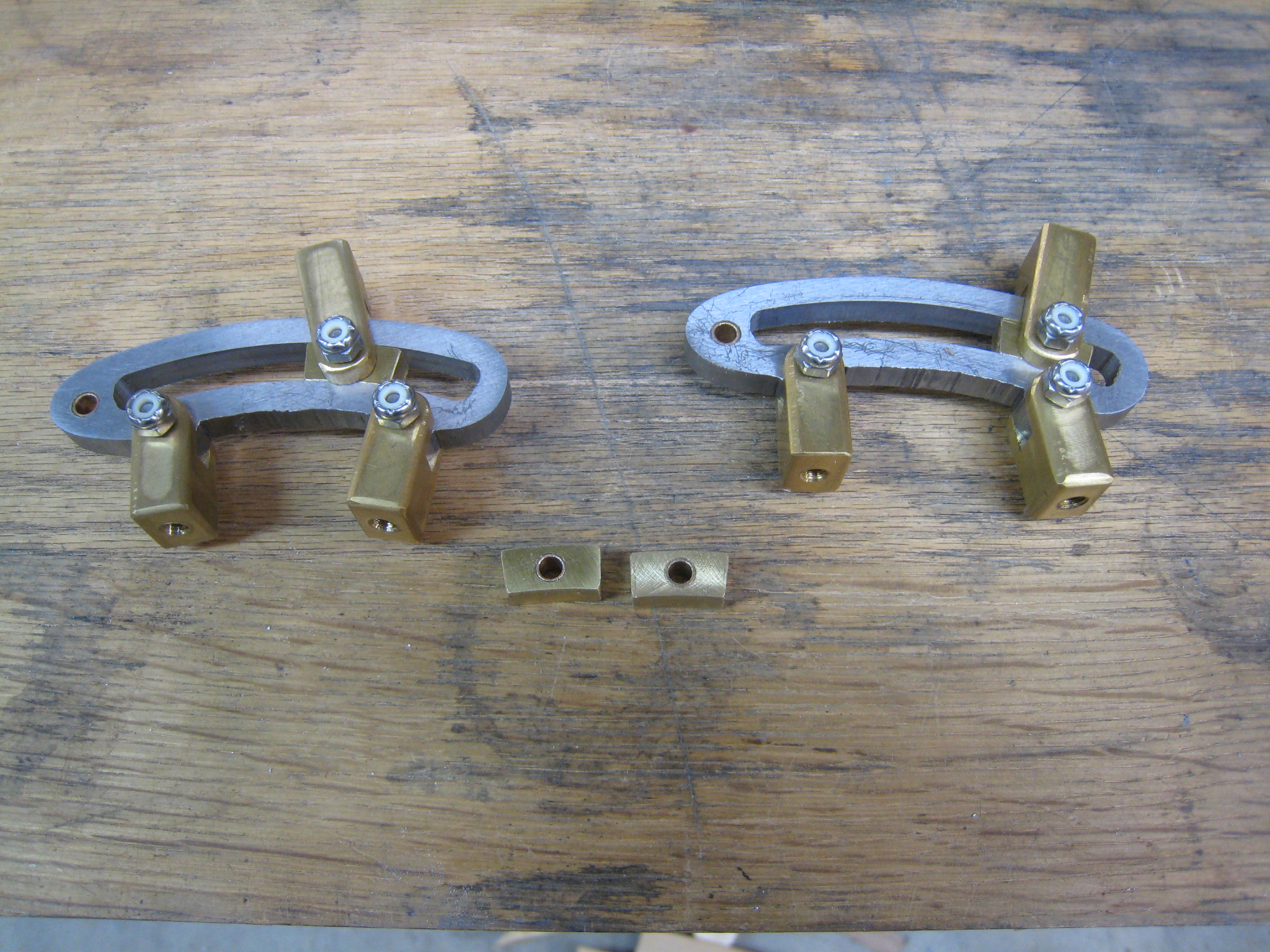
Partially shaped Eccentric Straps (8/2/09)
Shaped Eccentric Straps (8/2/09)
Shaped Eccentric Straps (8/2/09)
I am making 10 Eccentric Straps at one time.
Only 4 are needed for an engine.
It is much easier to make a lot at one time compared to making a few several times.
It is very important to have the rotary table square on the mill table or the first and last Eccentric Strap will be different sizes.
Thinning the Eccentric from 3/8" to 5/16" (8/9/09)
Squaring and centering the Eccentric for drilling/tapping (8/9/09)
Tapping the Eccentric (8/9/09)
Boring the Eccentric (8/10/09)
Piston valve (I left the hole at 1/4" as the threaded piston rod will be less than 1/4" OD.) (8/13/09)
Link Blocks in Links. All bearing surfaces have bronze inserts. (8/14/09)
The Valve Rod stem is made out of hot rolled steel plate. (9/5/09)
The Valve Rod is mounted on the Al Eccentric Strap. (9/5/09)
Next I started on the LP valve.
LP "D" valve with pocket on bottom. (10/25/09)
LP "D" valve with pocket on bottom. (10/25/09)
Shown is a blank, the "D" valve and a couple of cut off scraps. Since the LP "D" Valve is not symetric top to bottom, I scribed "TOP" and "BOTTOM" on the respetive sides.
I made new valve stem top covers using a straight thread insead of the 1/8" pipe thread that I put on the first ones that I made.
I made the LP Valve Surface including the exhaust and cylinder ports.
The LP Steam Chest has 2 allen cap screws to hold it on without the cover studs and nuts.
The following four pictures are taken without the "D" valve in the Steam Chest. The LP Eccentric Straps are too tight or bind. I will have to figure this out later.
Engine from the HP (bow) end. (11/17/09)
Engine from the Starboard side. (11/17/09)
Engine from the LP (stern) end. (11/17/09)
Engine from the Port side. (11/17/09)
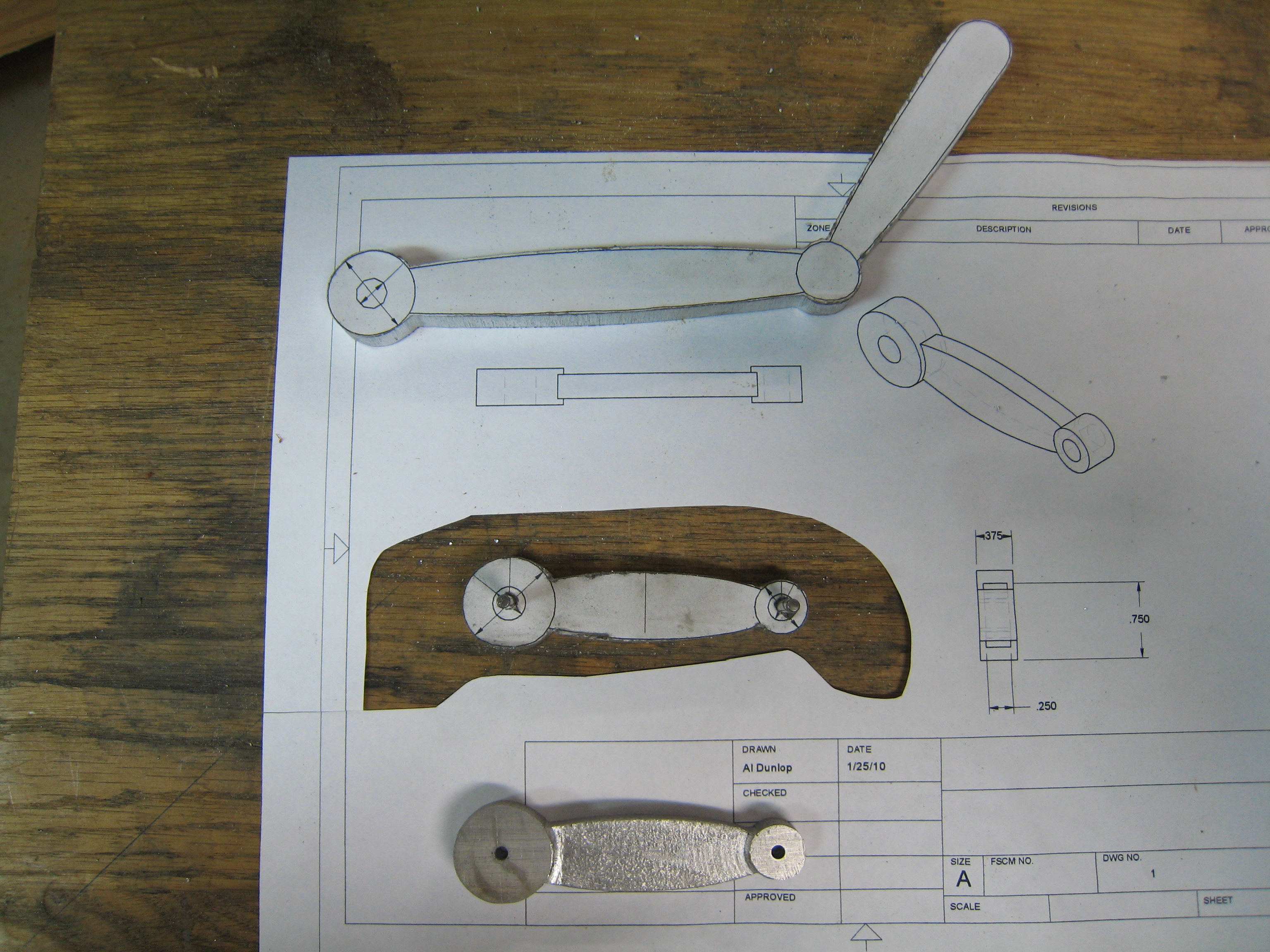
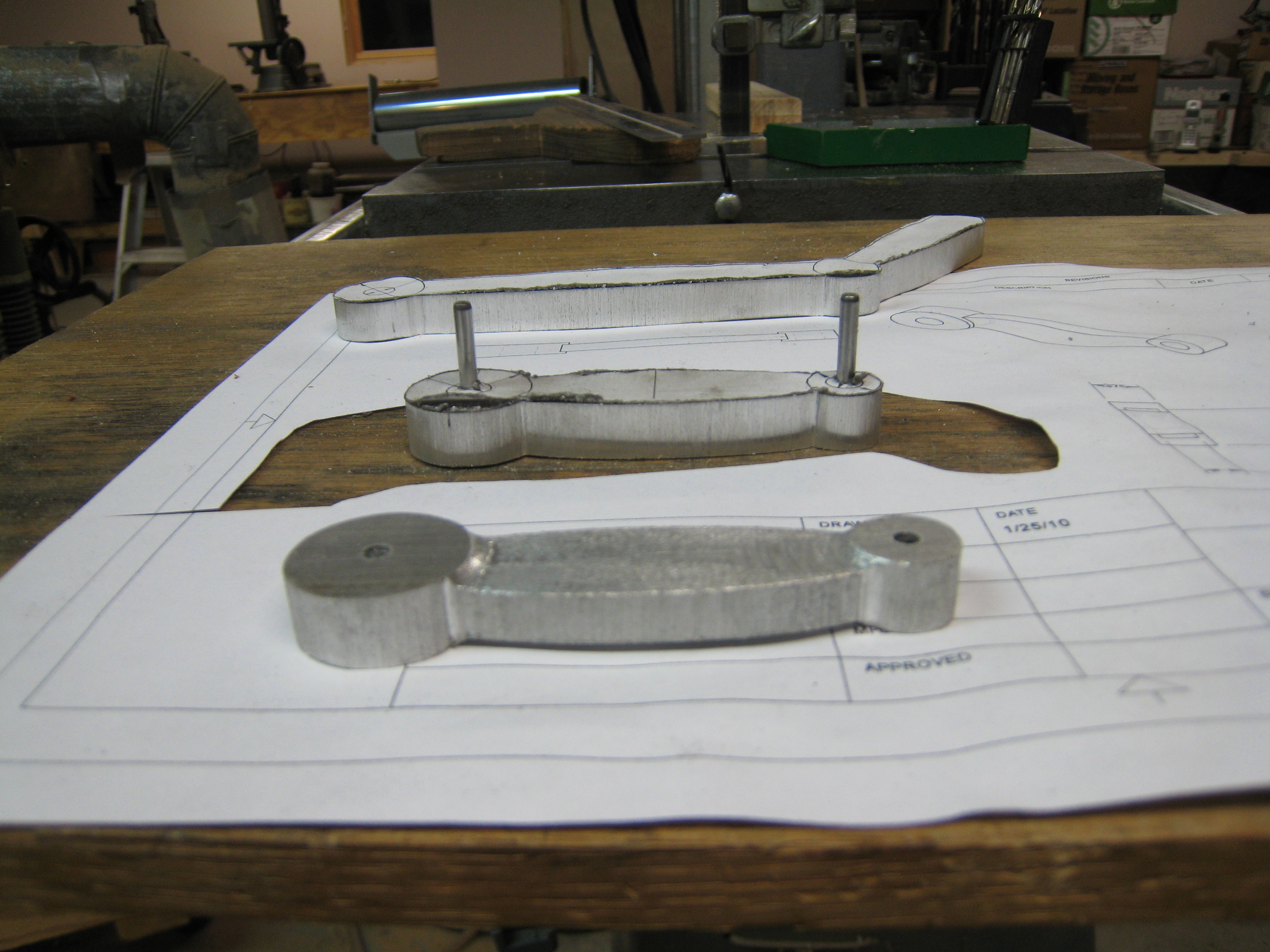
Shifter handle and first link. (1/27/10)
Shifter handle and first link. (1/27/10)
Shifter handled, first link and second link. (1/27/10)