This is the case for the boiler that I started back in 2011.
It is fairly similar to the case that I built for my boiler that I built back in 1994.
There are some small differences based on the difficulties I had last summer removing the case of my earlier boiler.
[In the summer of 2013, I thought that I had a very small leak in my almost 20 year old boiler.
I proceeded to take the case off and found that essentially all the stainless screws were very difficult to remove.
I twisted off several brand name (guaranteed for life) screwdrivers.
This caused me to get some blisters and calluses on my hands.
I was limited to removing about 1 to 2 screws per day.
Once a screw started to wiggle, it would take about 10 more minutes of turning it back and forth to remove it.
Eventually I go out the angle grinder and took the heads off.]
[It turned out that the leak was in the threads of the pipe.
New pipe dope and 150% hydro verified no leak.
(This was a huge amount of work for nothing.
Always try the easy things before the time consuming things.)]
With this in mind, I wanted this new boiler to have a much easier case to uncover the pressure vessel.
Concept
The general concept is a case with about 0.030" Stainless inner jacket, 1" fiber refractory insulation, 0.030" Aluminum and finally 1/2" white oak lagging.
I wanted to avoid having the screws get too hot, and simplify opening up the boiler.
I decided to have the pressure vessel mounted on the Base of the housing.
The outer shell would be bolted into the side of the Base with no other attachment.
This would mean that removing the pipe connections to the boiler and the screws around the Base would allow the whole shell to be removed.
The grate and Pressure Vessel mount will be directly to the Base.
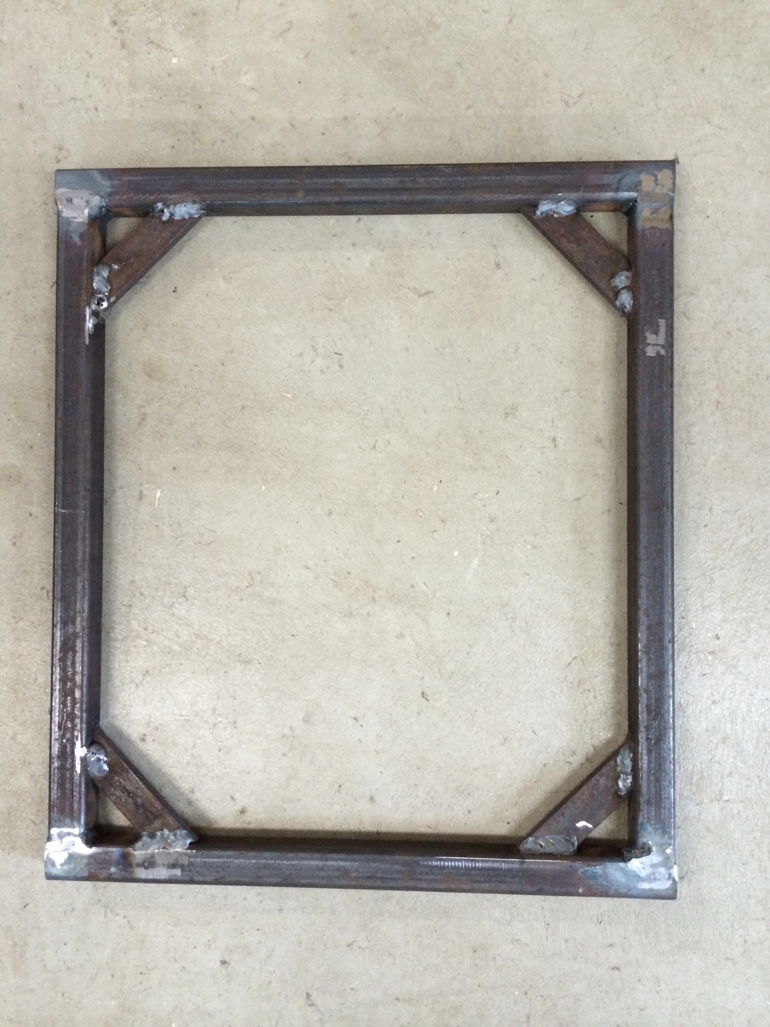
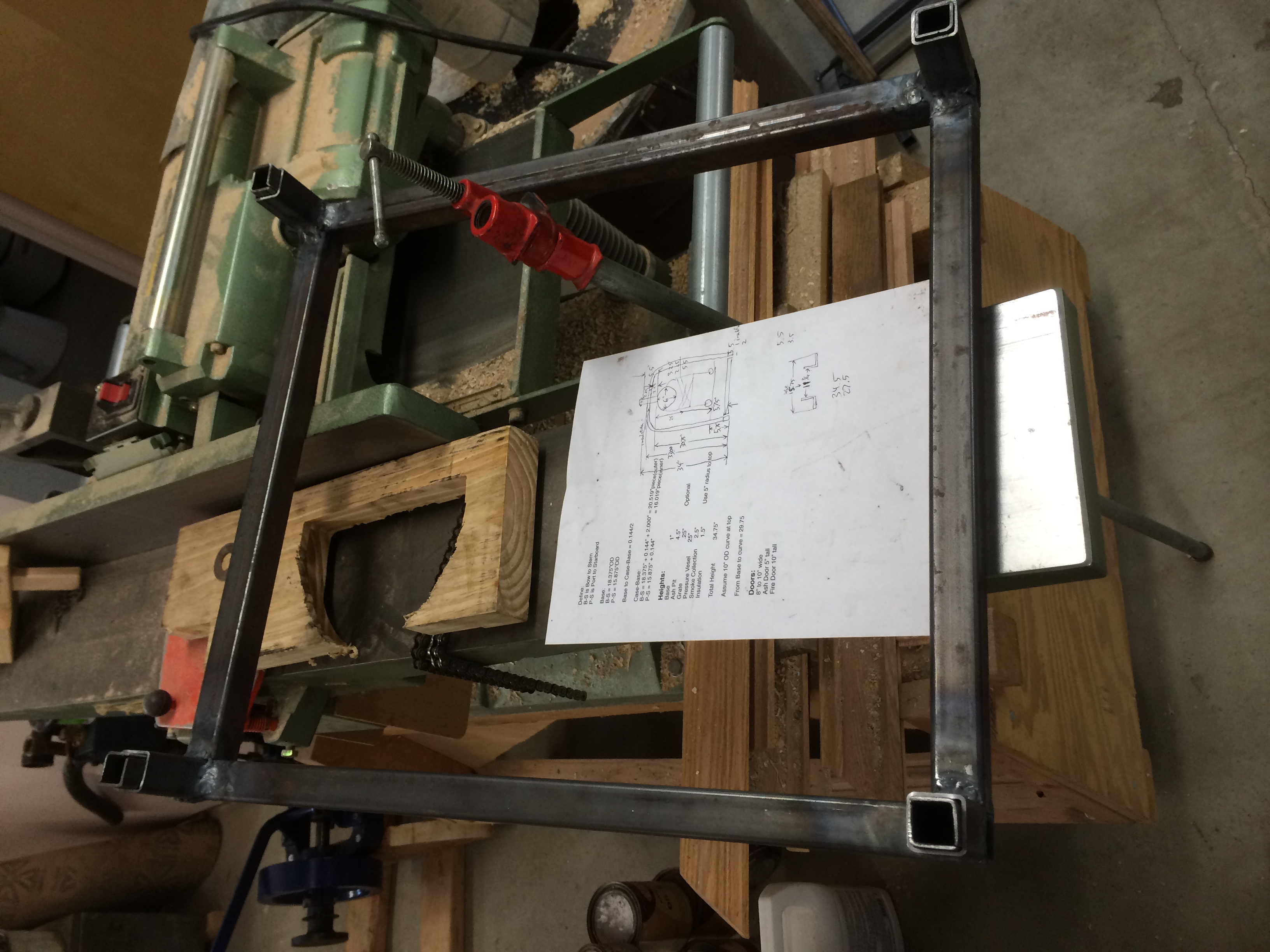
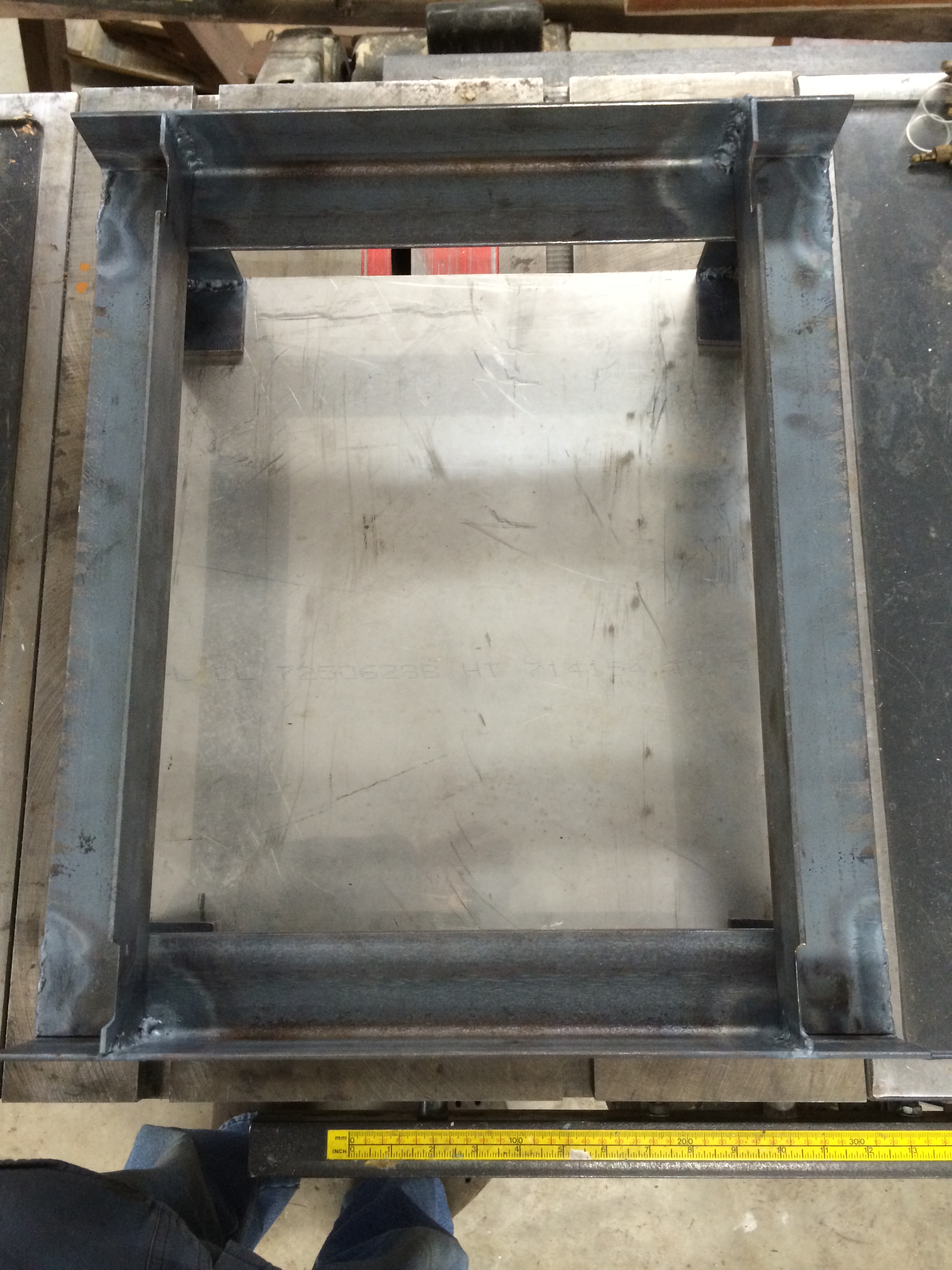
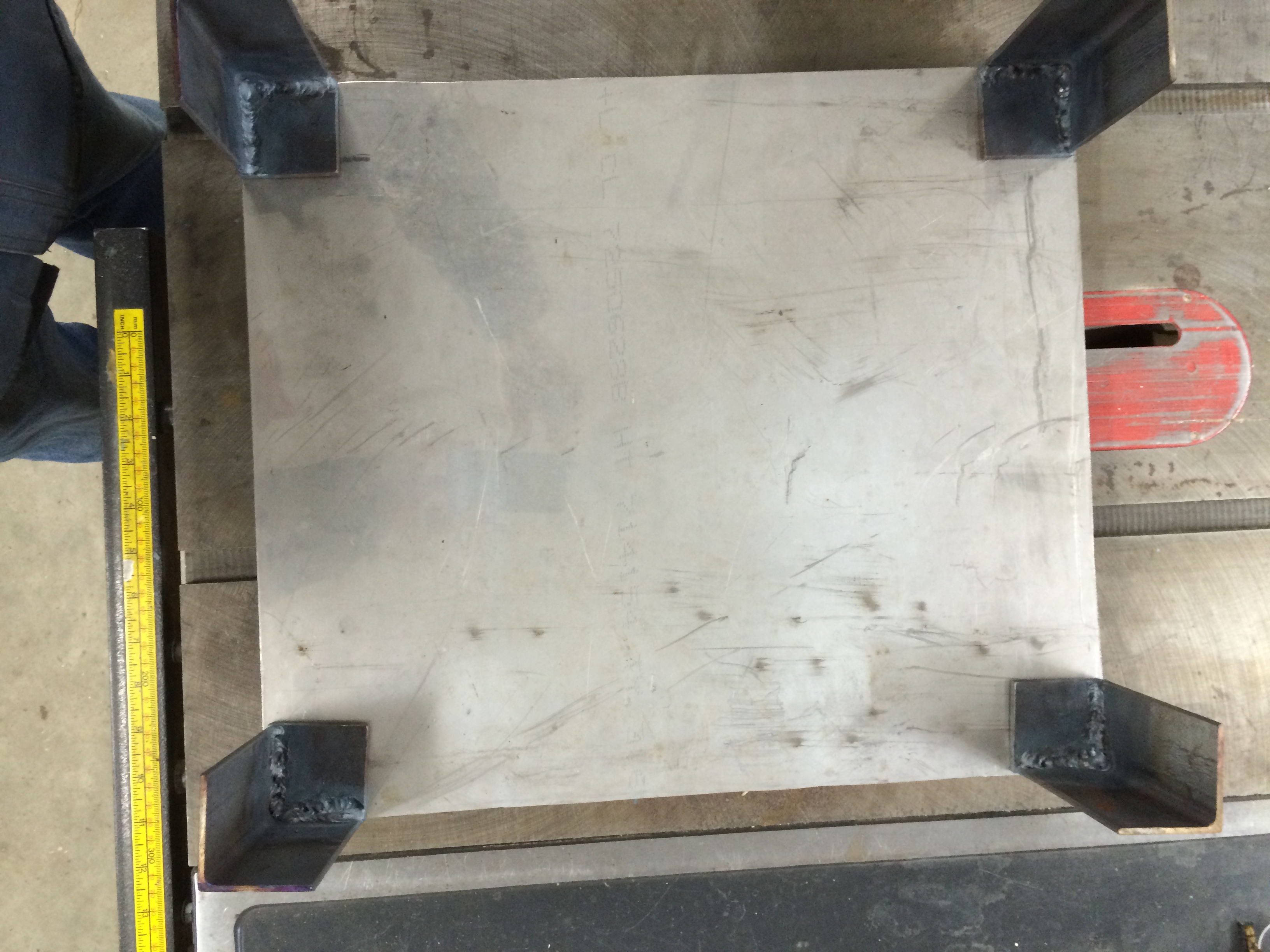
Base
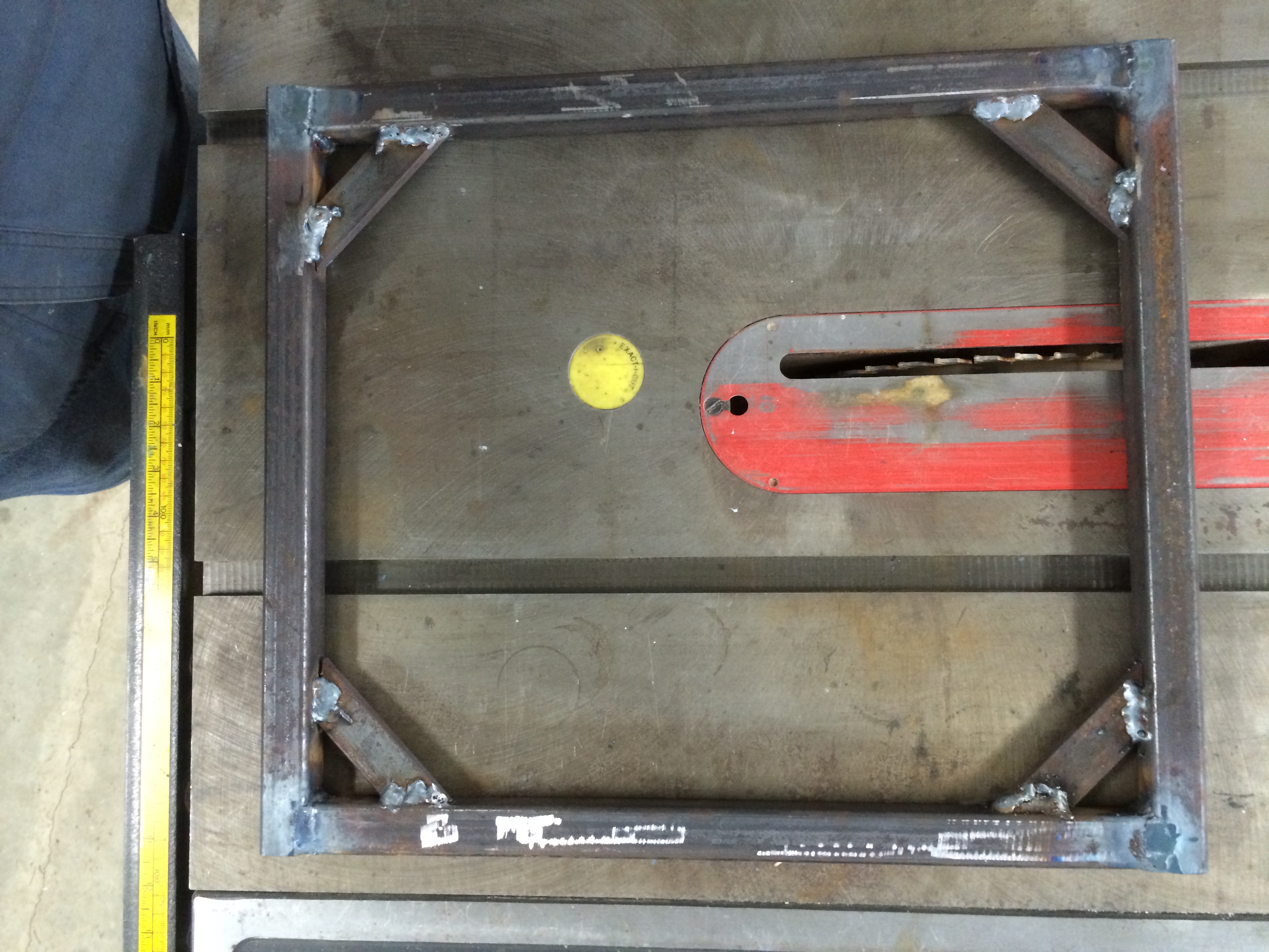
The Base is made from 1" square tubing with 1/8" wall.
It is the inner rectangle in the picture with 4" diagonals for bracing.
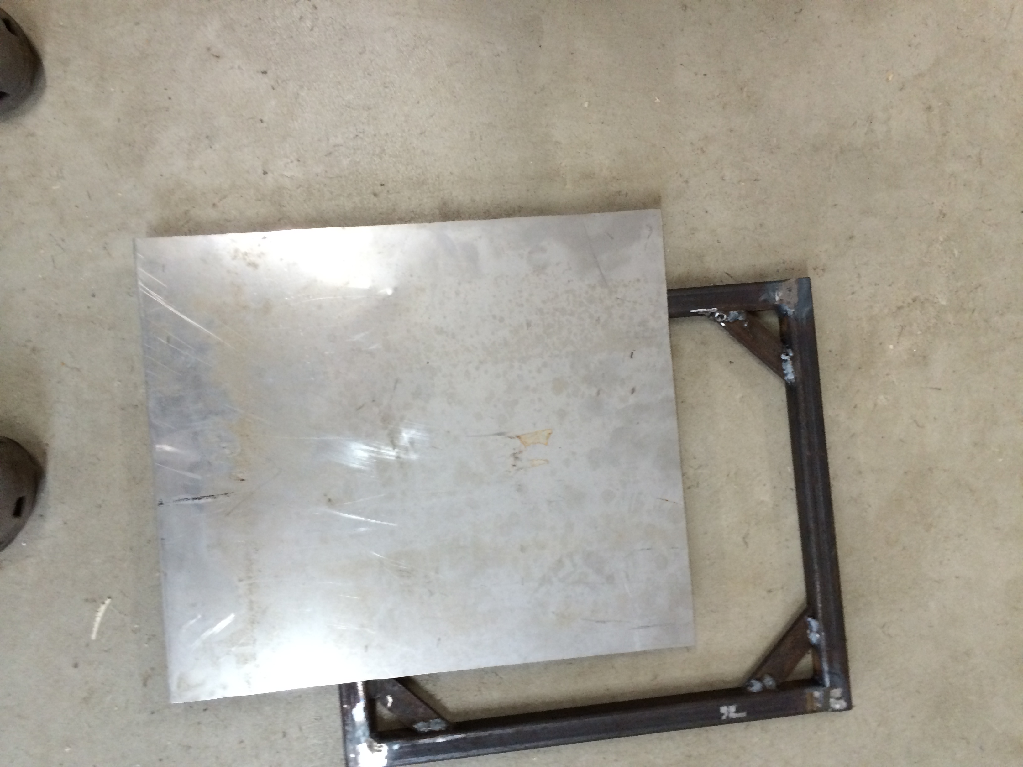
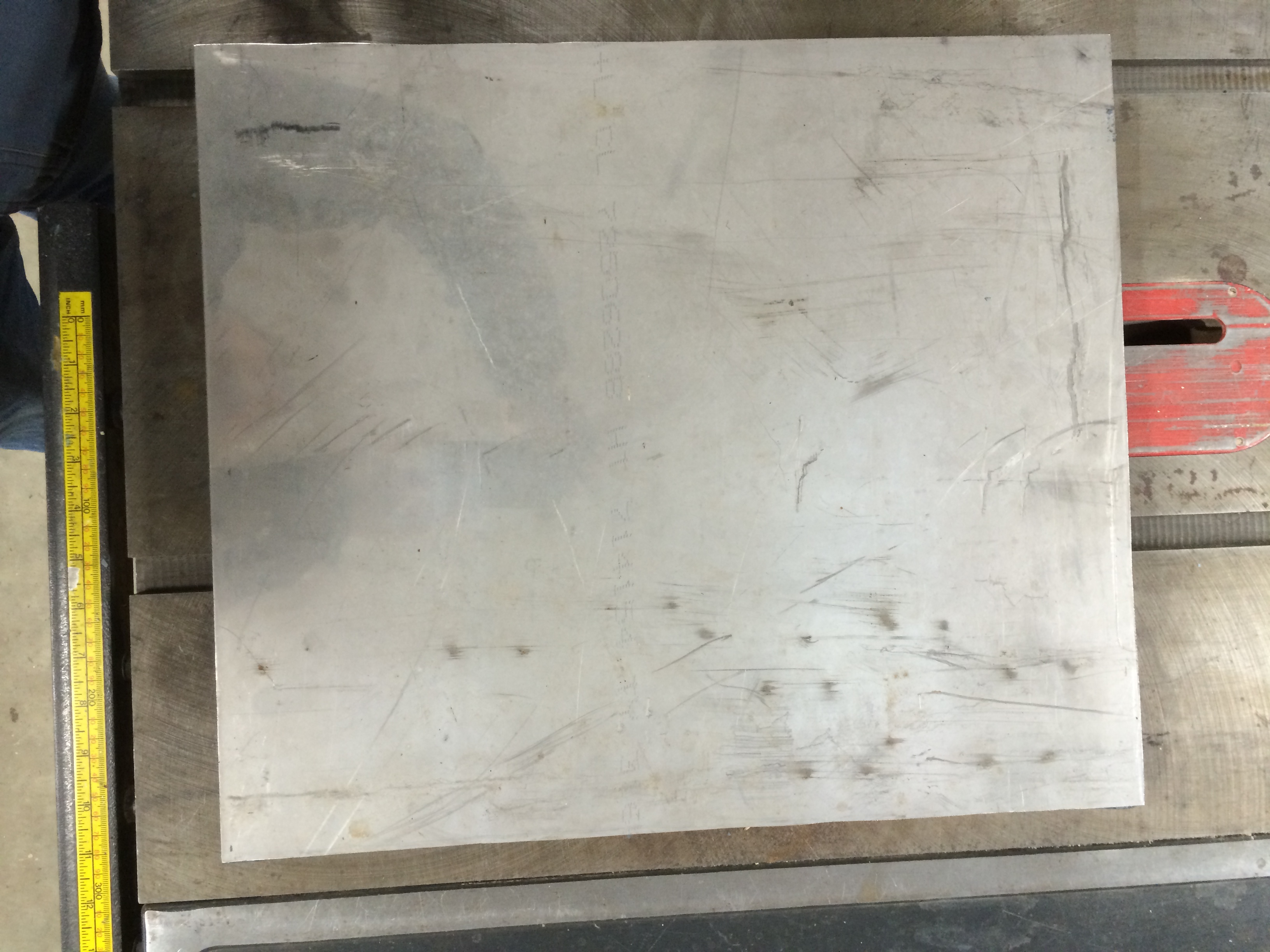
The Stainless covering the Base is about 1/16" thick and will cover the Base.
Boiler Base (3/26/2014) (I am out of practice welding. The welds get better as I do more.)
Base plus cover (3/26/2014)
Case
The case is made out of 1" square tube with 0.083" wall.
The SS will go inside, the aluminum outside.
The bottom of the case will screw into the outside of the Base with the SS wrapping under the square tube at the bottom of the case.
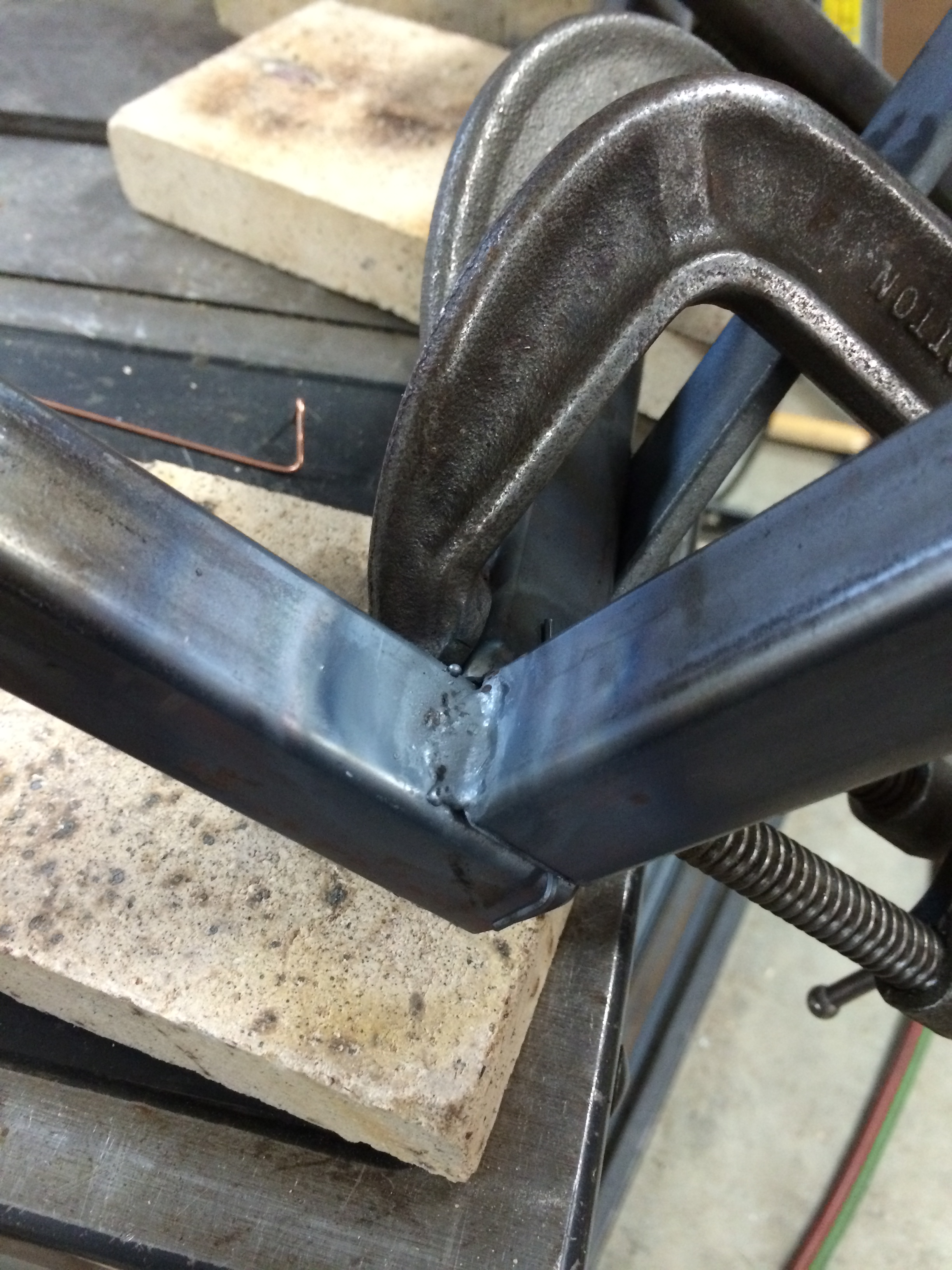
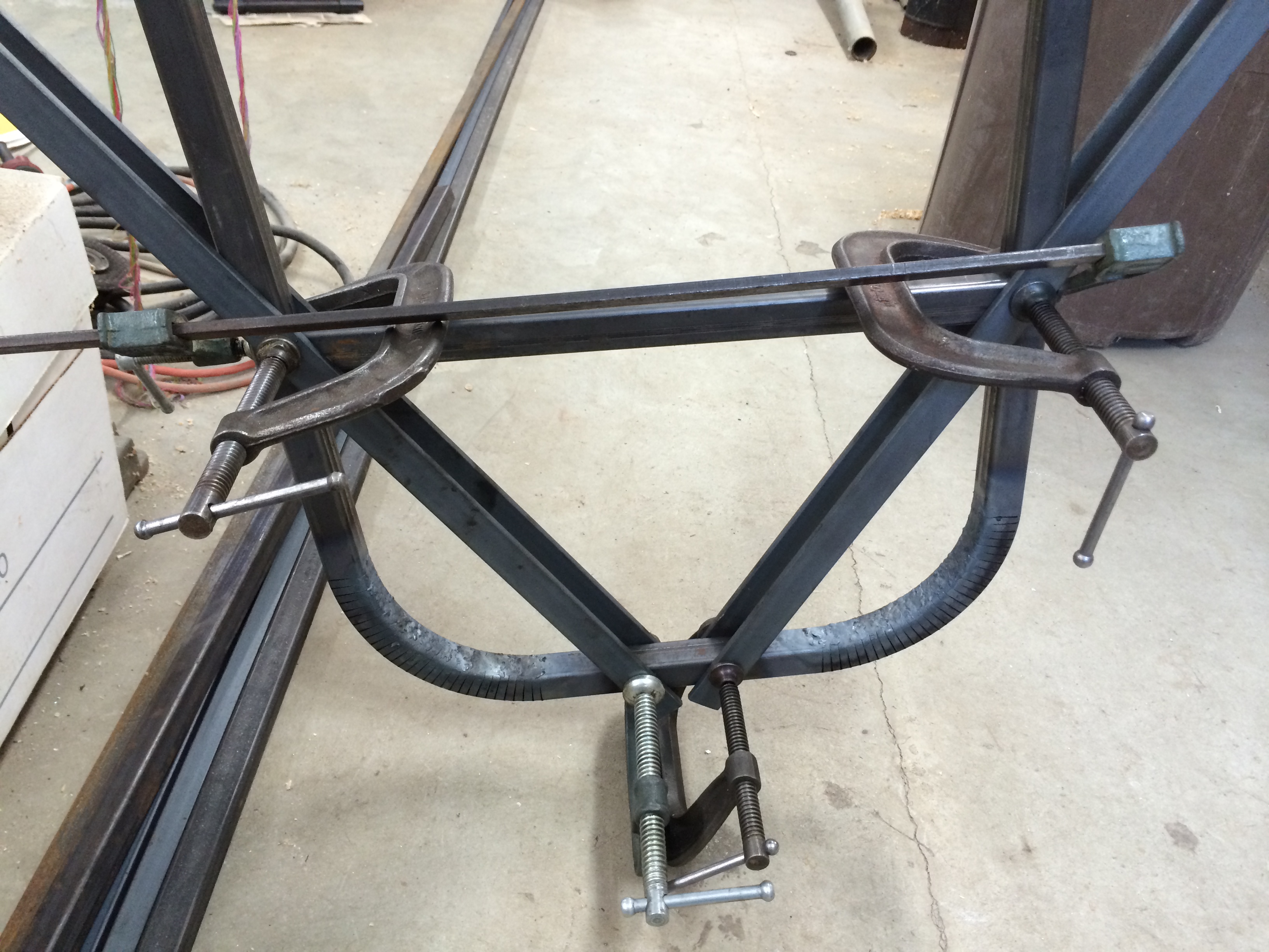
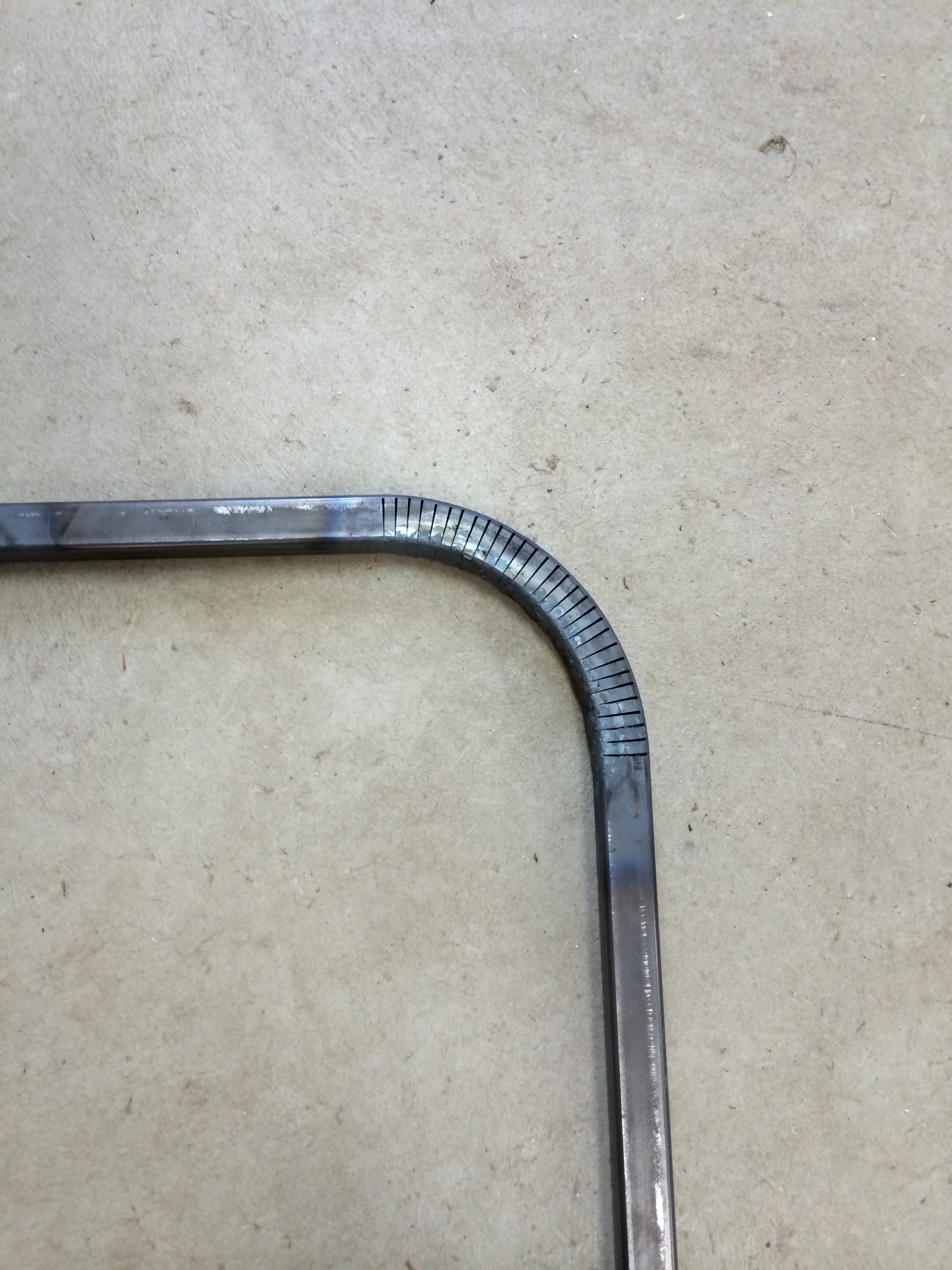
Thirty cuts made the 5" radius curve at the top of the case.
The cuts are then gas welded back together strengthening the curves.
There are a lot of cuts 30 * 4 = 120.
It was interesting welding the slightly larger that 0.2" wide strips of thin metal back together.
(I only made one hole that I had to fill in.)
I used a #2 tip oxyacetylene torch for all the work on the 0.083" square tubing.
Case Curves clamped for welding (3/25/2014)
Case Curve (3/25/2014)
The bottom of the case s 1" square tubing that surrounds the Base.
It is 0.083" walled tubing.
There is sufficient space between the Base and the bottom of the case for the Stainless Steel sheet metal to go between and wrap under the bottom of the case.
The bottom of the case was gas welded using the square Base as a guide.
Bottom of the Case (3/25/2014)
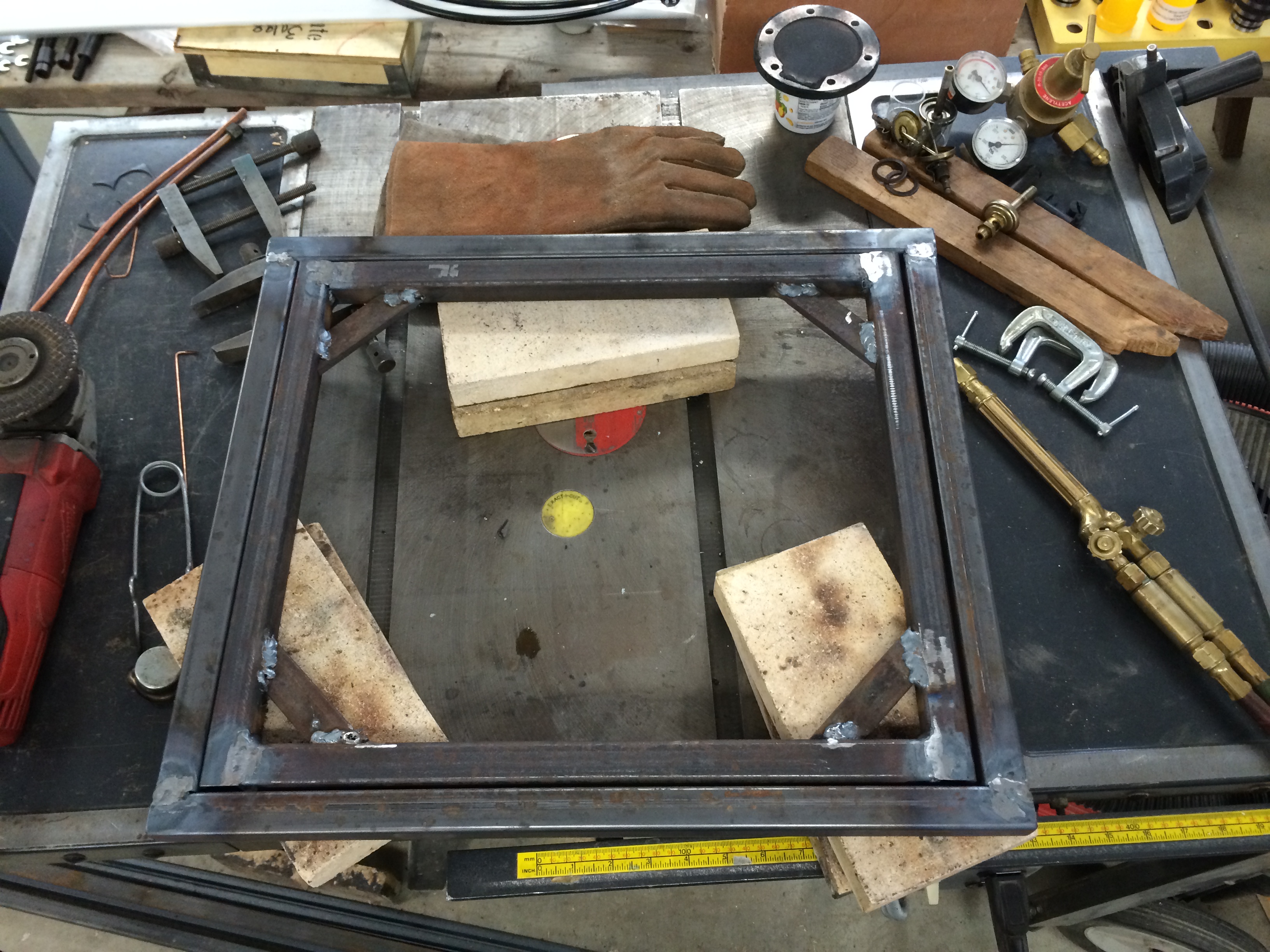
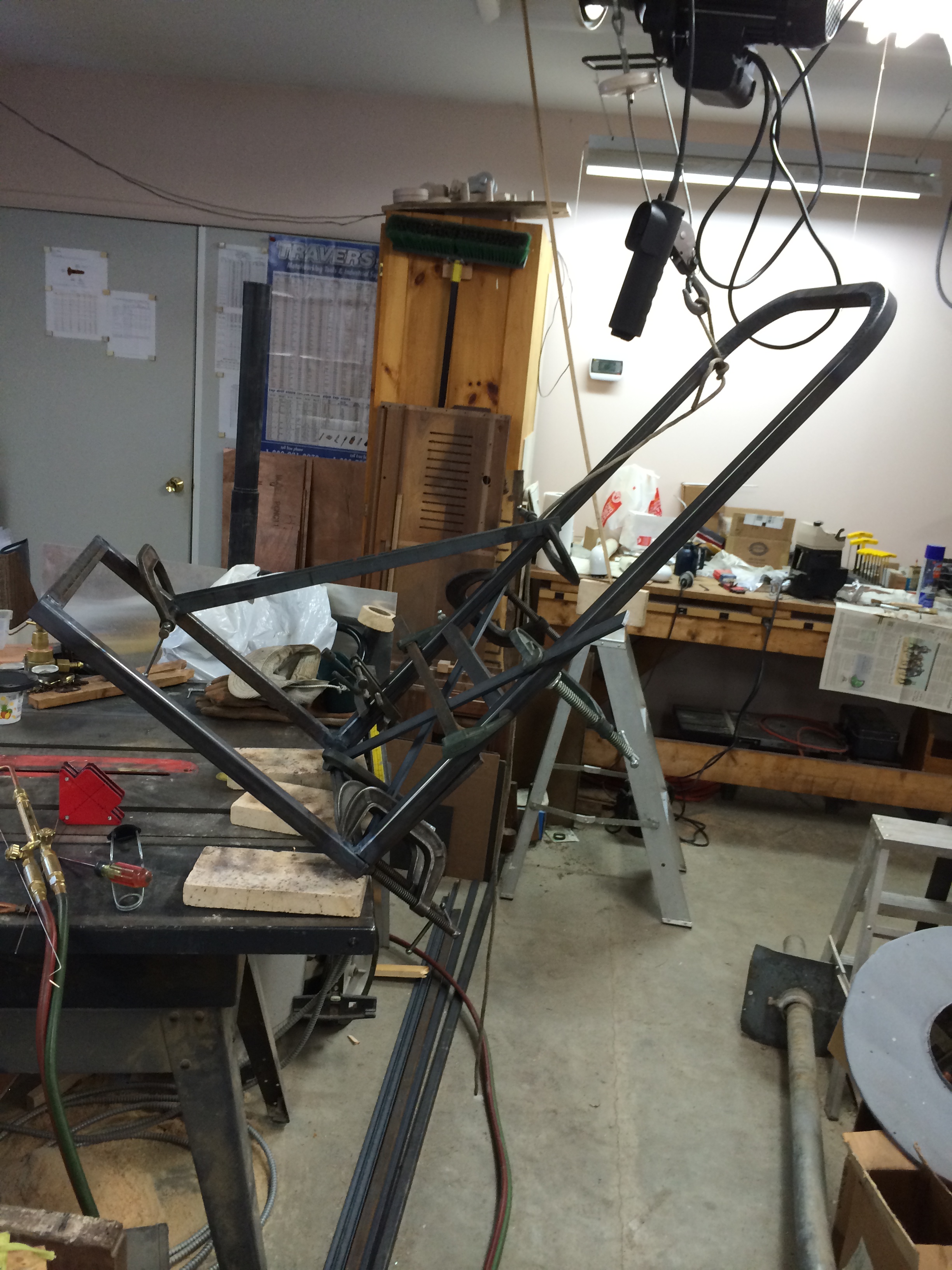
Next the bottom of the case is welded to the ends with the curved tops.
It is important to get this all square to look good and avoid problems when putting the sheet metal jackets on.
All 4 sides of the square tubing are gas welded.
The sides that will receive sheet metal will be ground flat.
Case End clamped for welding (3/25/2014)
Case End clamped for welding (3/25/2014)
Case welding (3/25/2014)
It was just after welding both ends on the bottom of the case that I realized that I had left a little extra tubing on the ends of the curved case ends.
This means that I will have to cut a piece out of each corner square tube.
Looks like I get more practice welding...
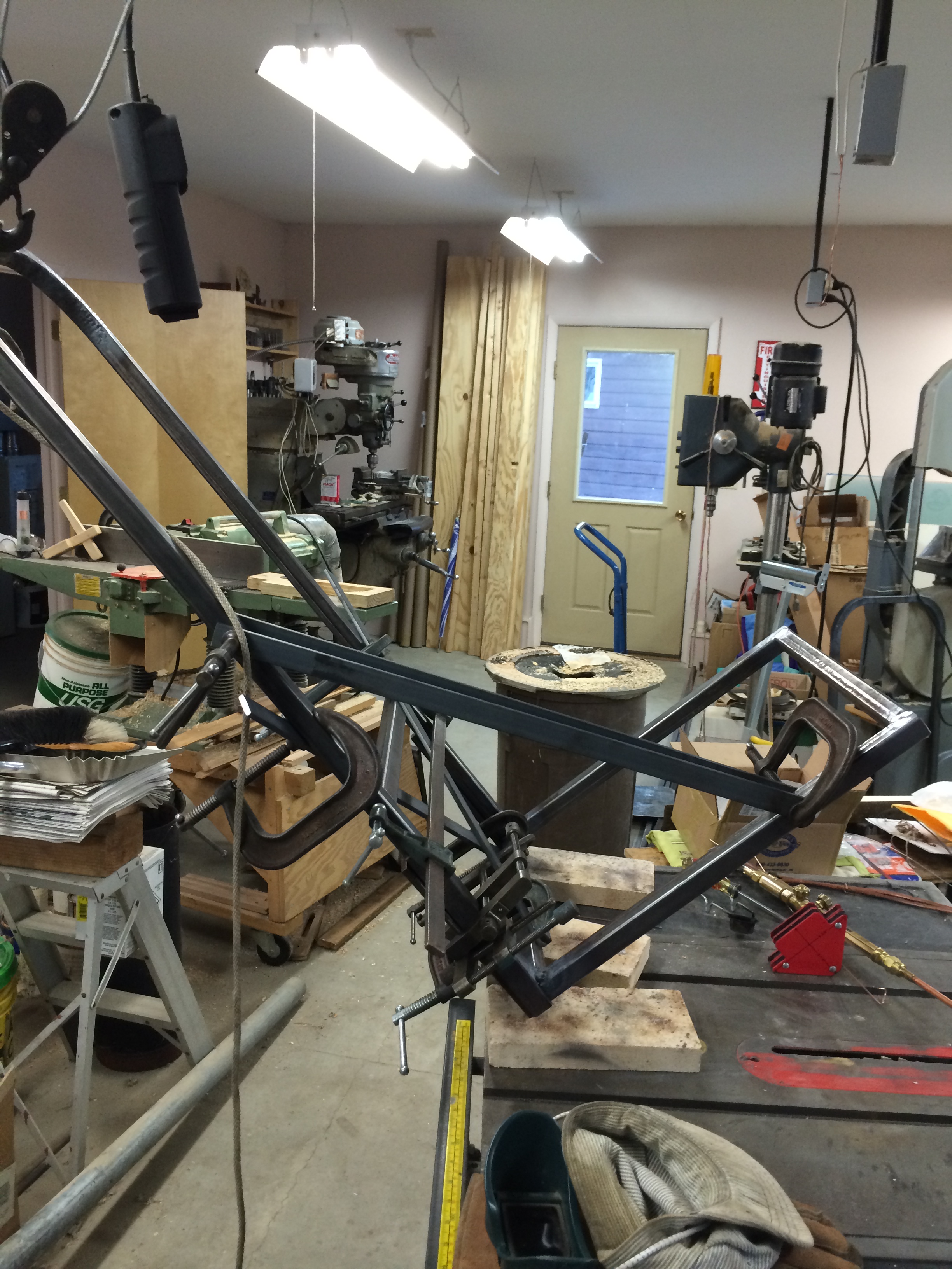
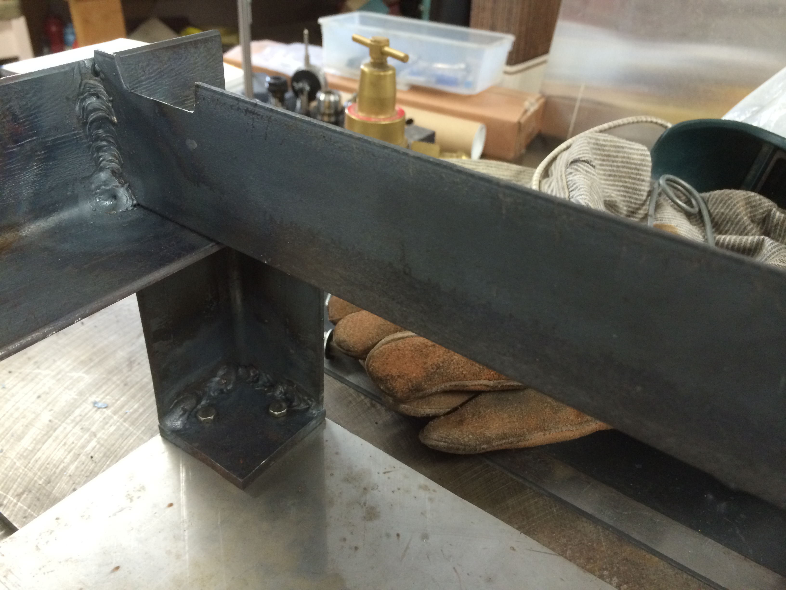
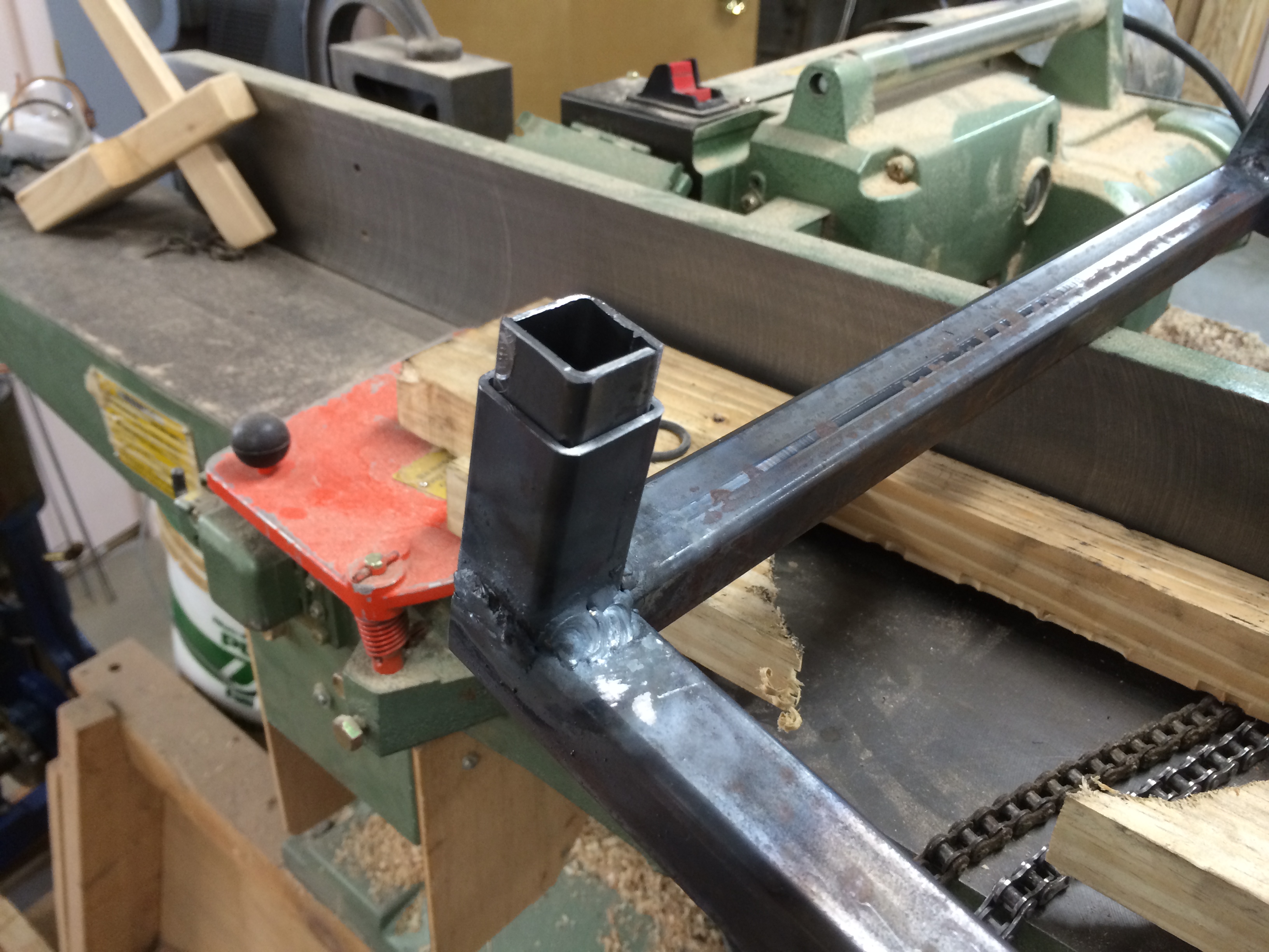
I decided to start on the stand that holds the Pressure Vessel.
This will bolt to the base.
Here is a top down sequence of the Stand and Base.
Base,Stainless, Legs and Pressure Vessel Holder. (3/30/2014)
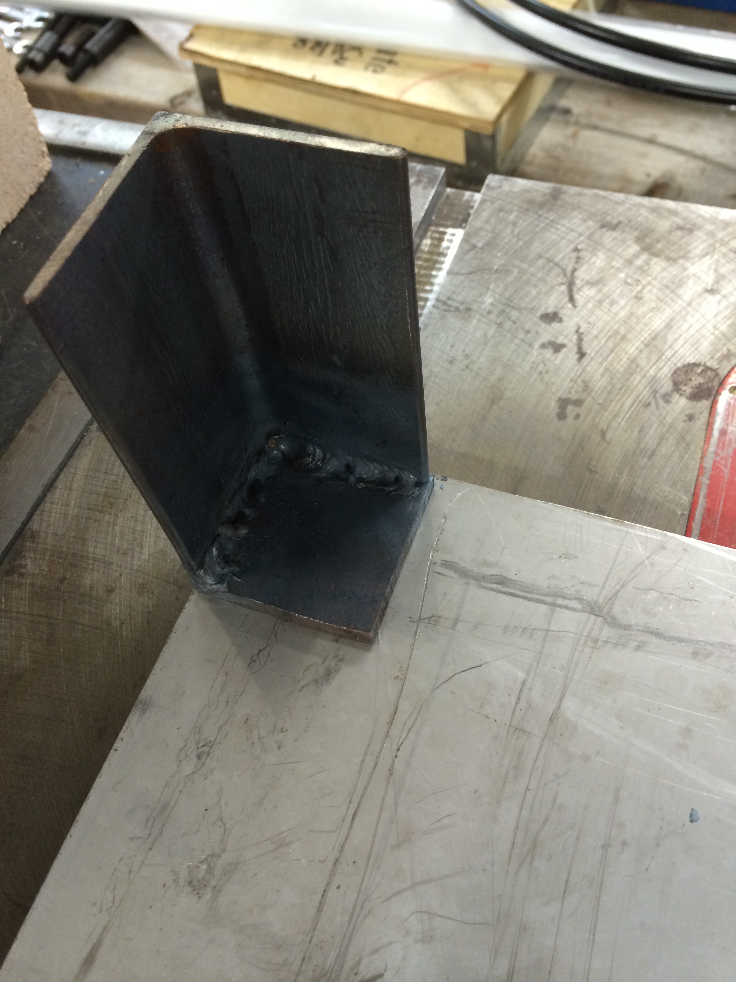
Legs (3/30/2014)
Leg (3/30/2014)
Stainless (to be under fire brick) (3/30/2014)
Base (3/30/2014)
Bolted down Legs. (3/31/2014)
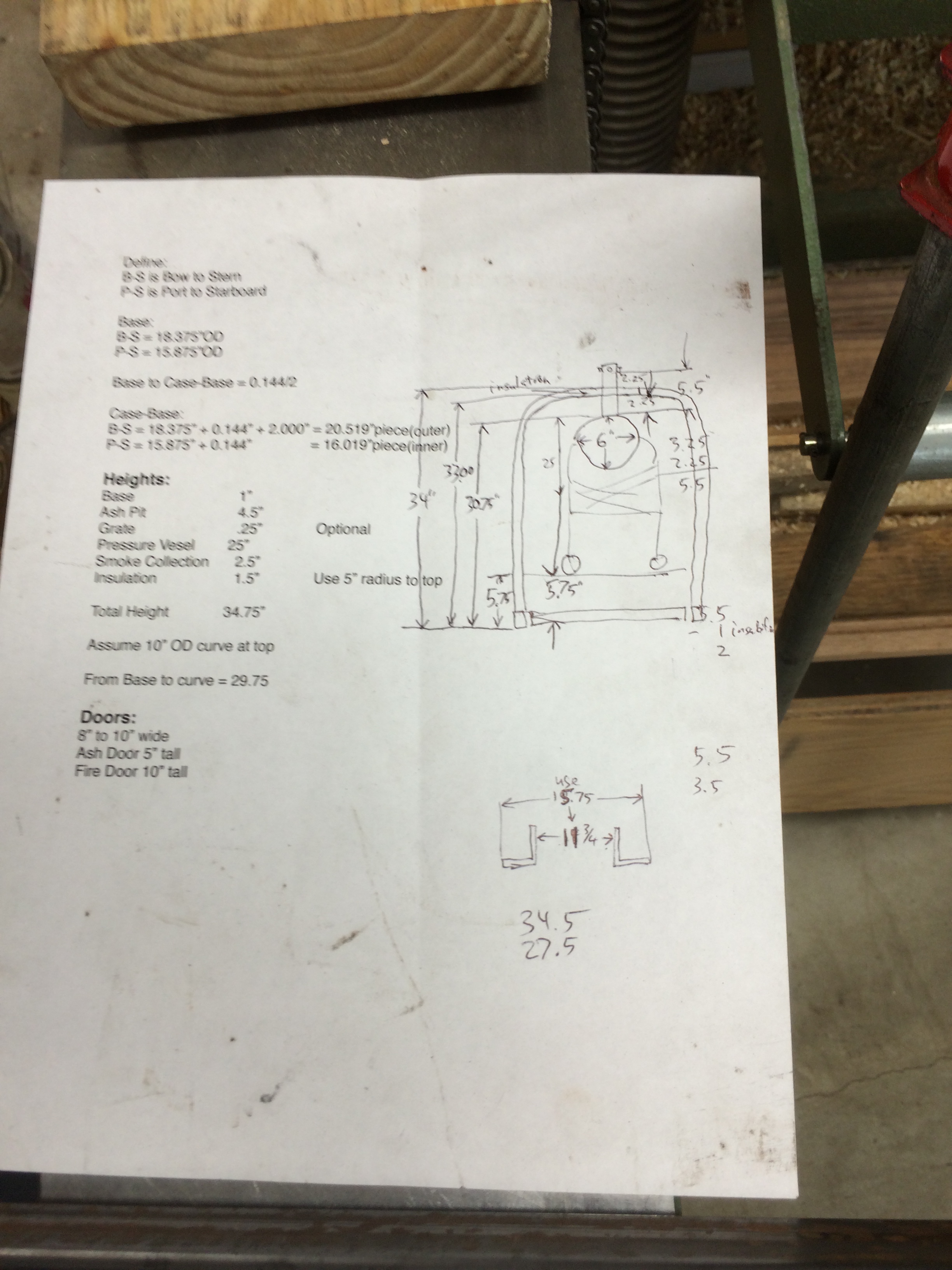
Heights (3/31/2014)
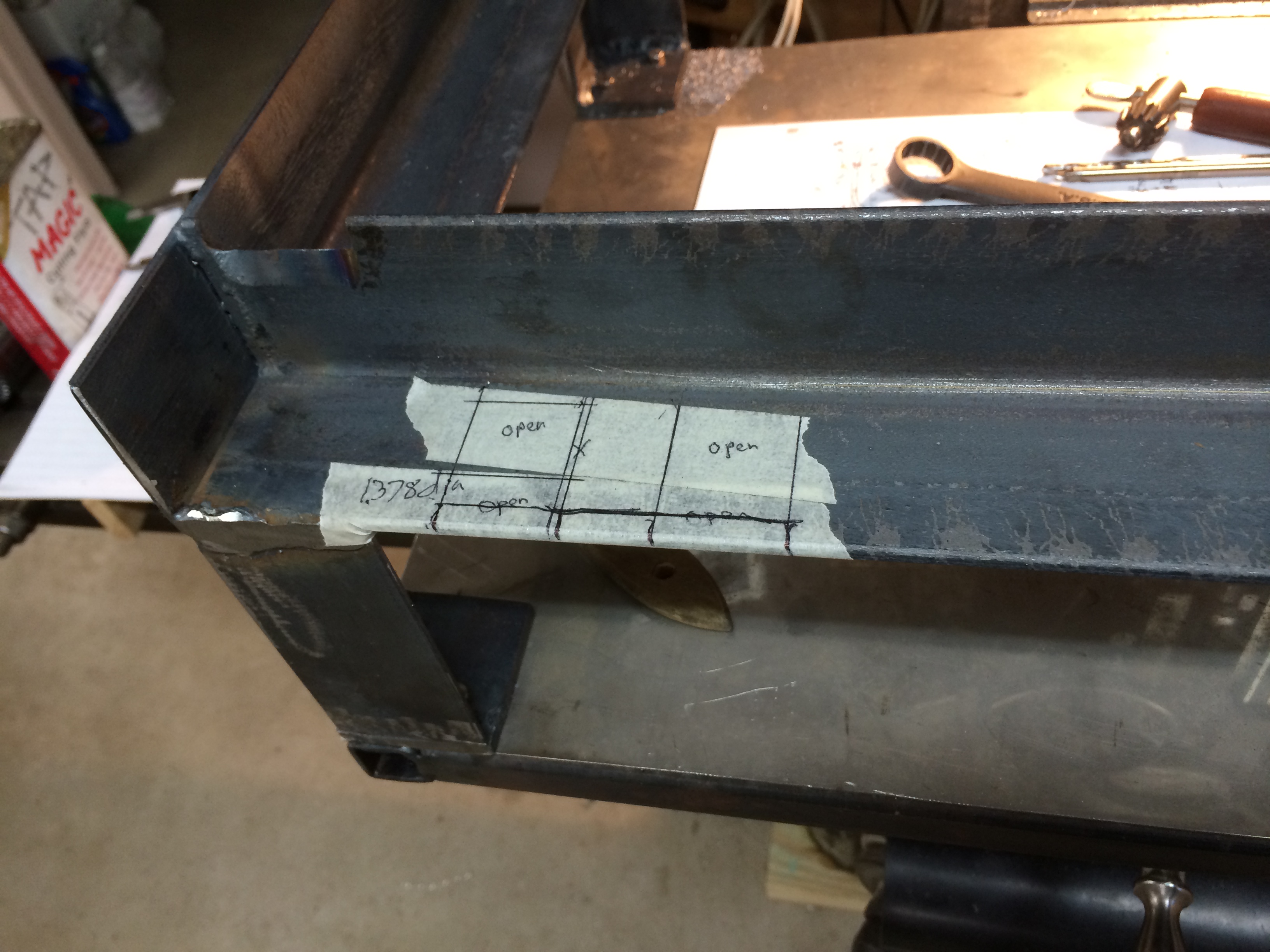
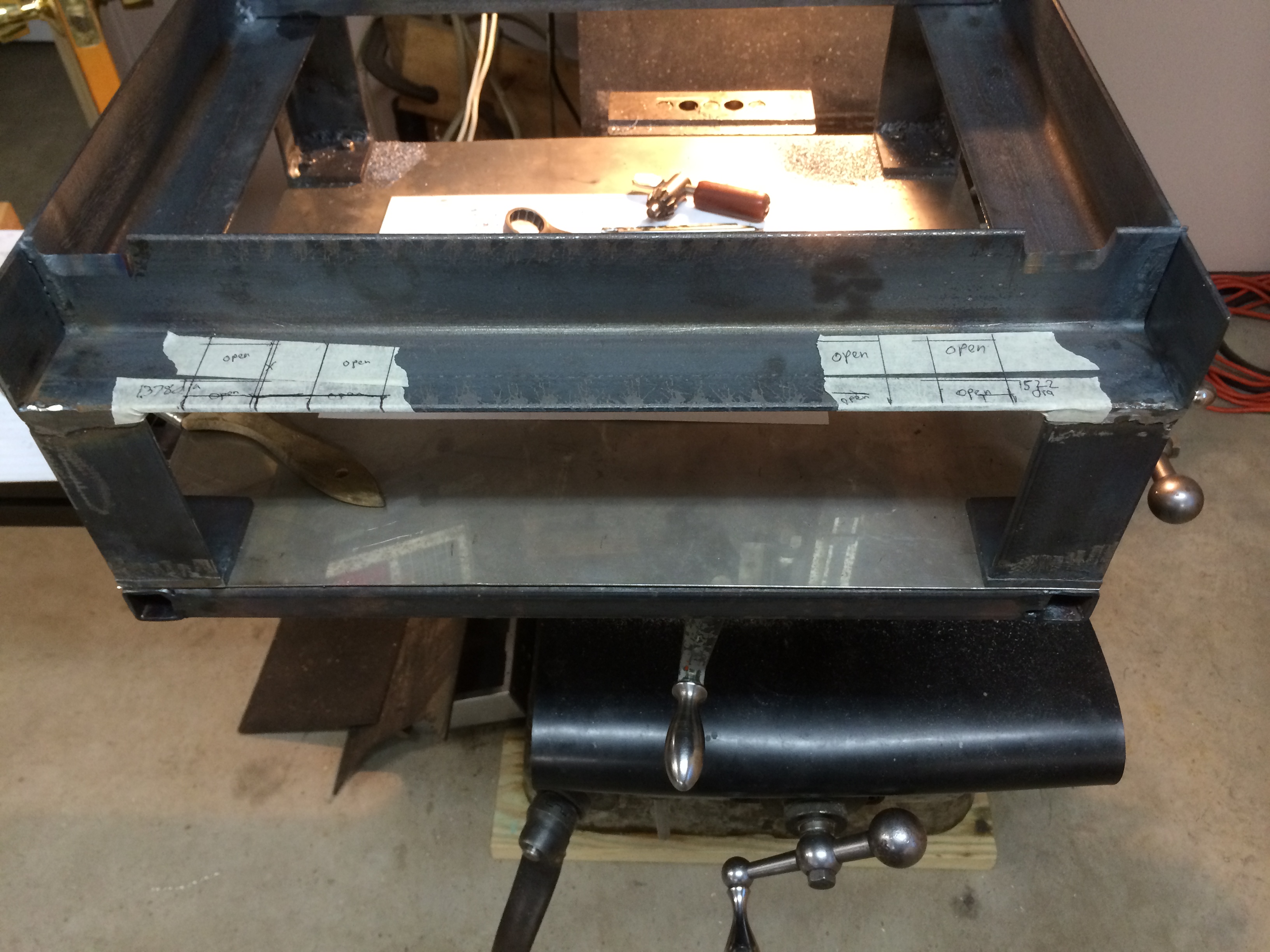
Cut Case with inside tube (3/31/2014)
Cut Case with inside tubes (raised before welding). (3/31/2014)
Marked for Pressure Vessel hold down. (3/31/2014)
Marked for Pressure Vessel hold down. (3/31/2014)
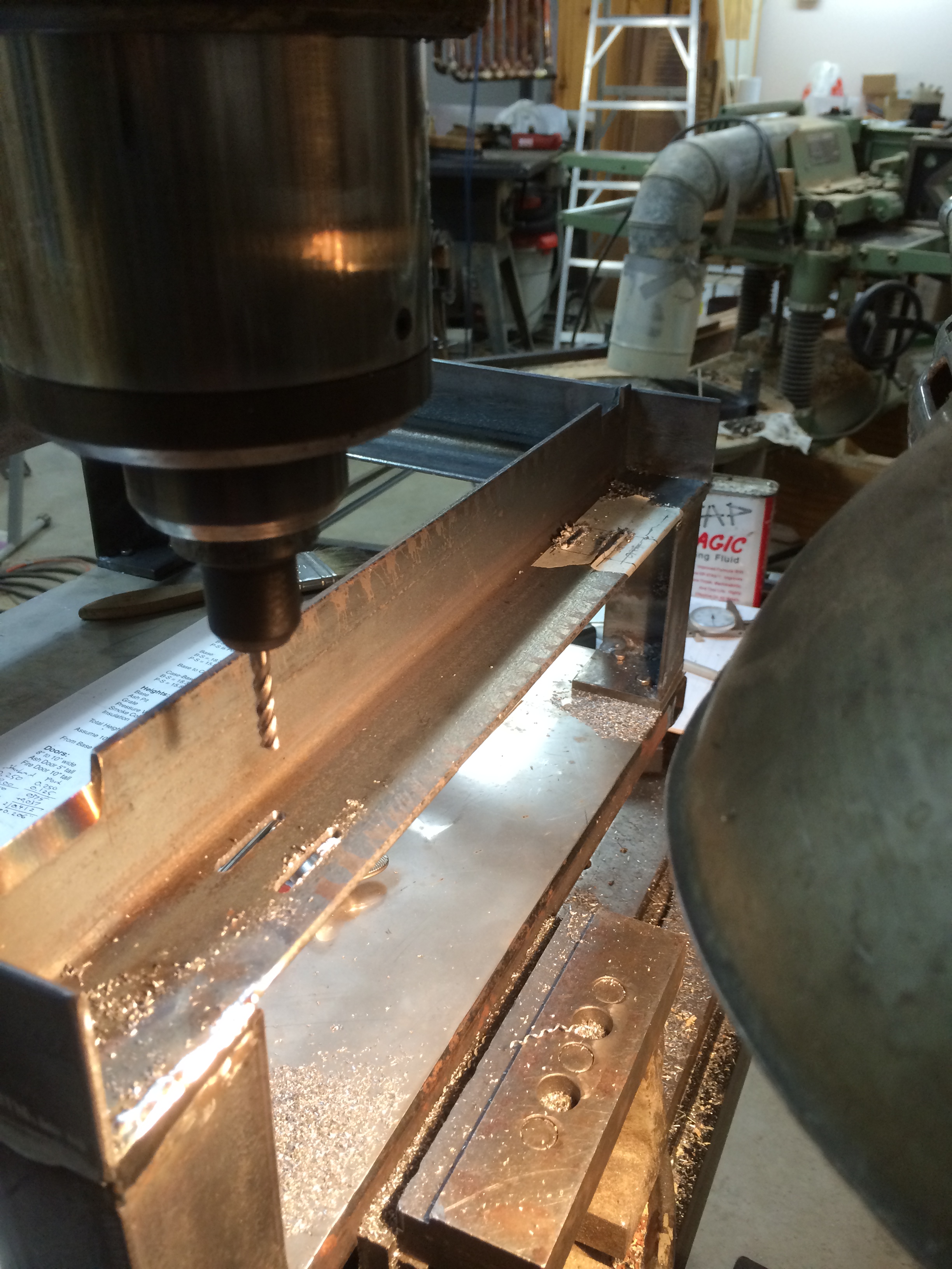
I had to machining a narrow slot very close to the angle of the 2" angle.
I did this with a 3/16" end mill verrrry slowly.
Since the EM had its tips broken already.
I predrilled and put it slightly through the hole.
The 8 slots went without any problems.
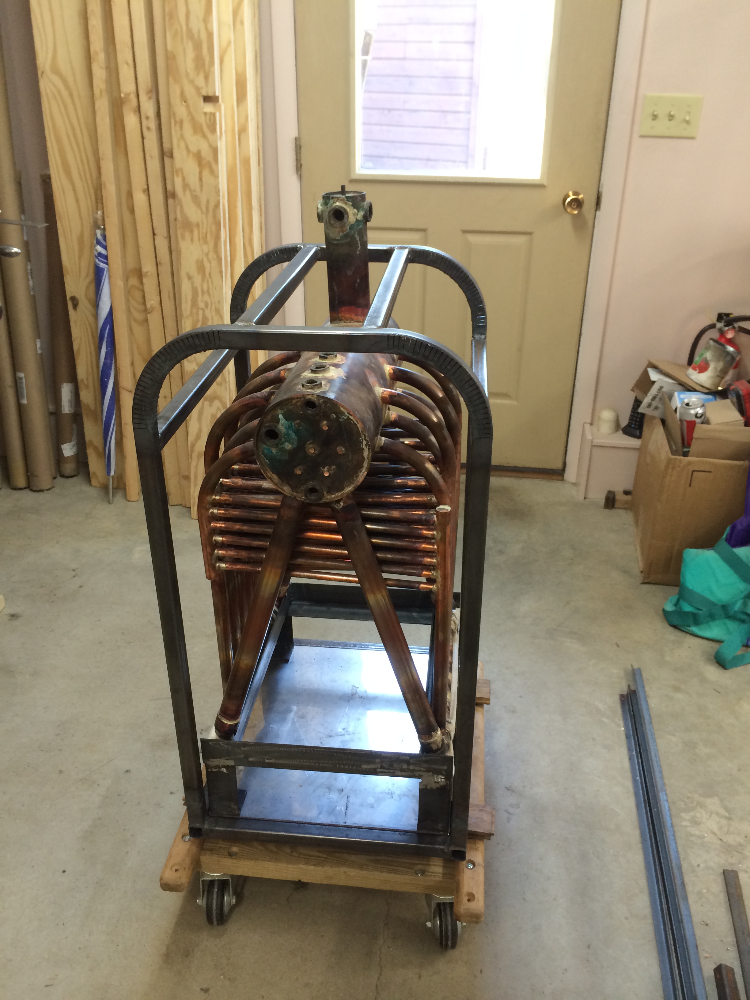
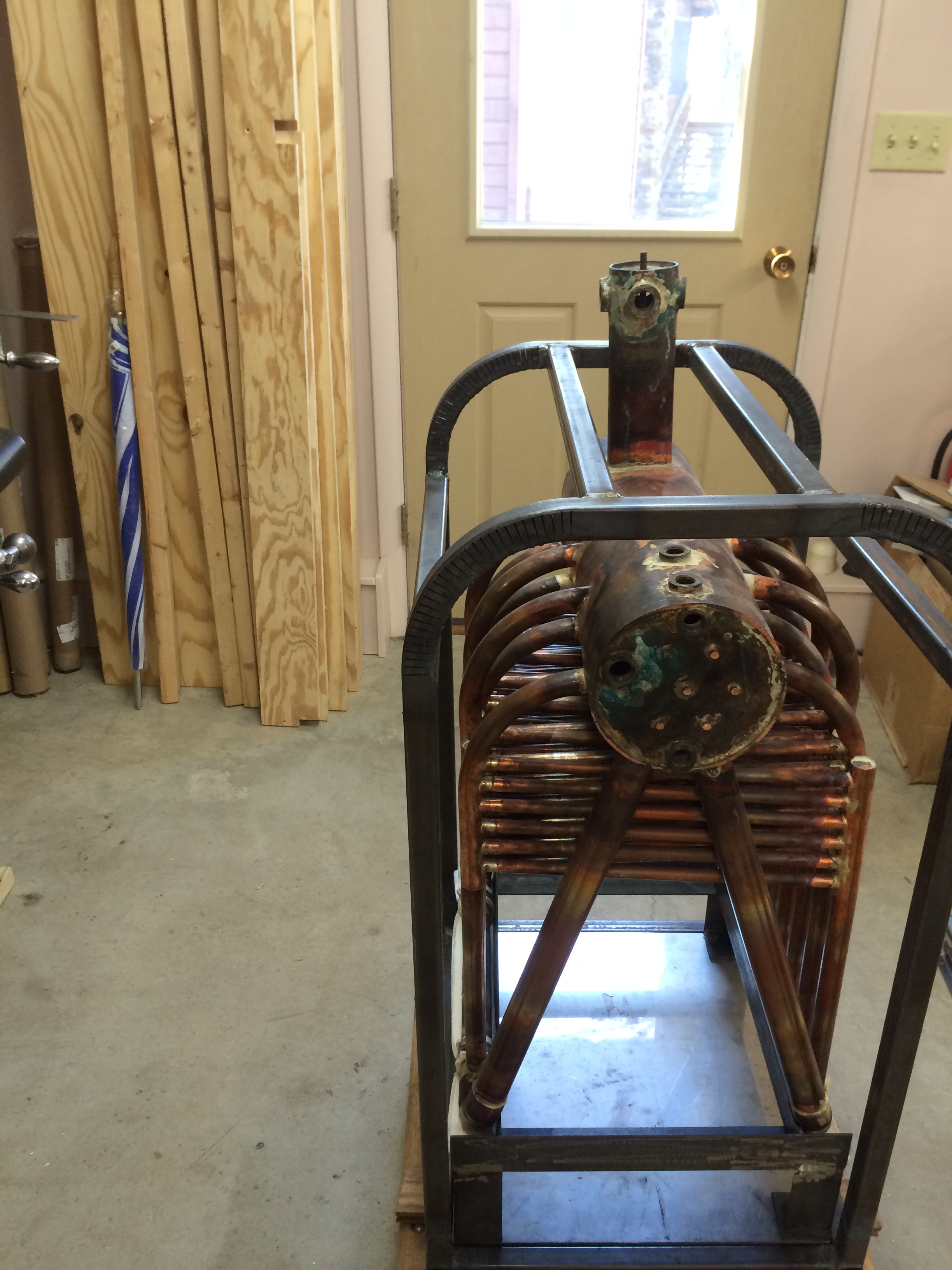
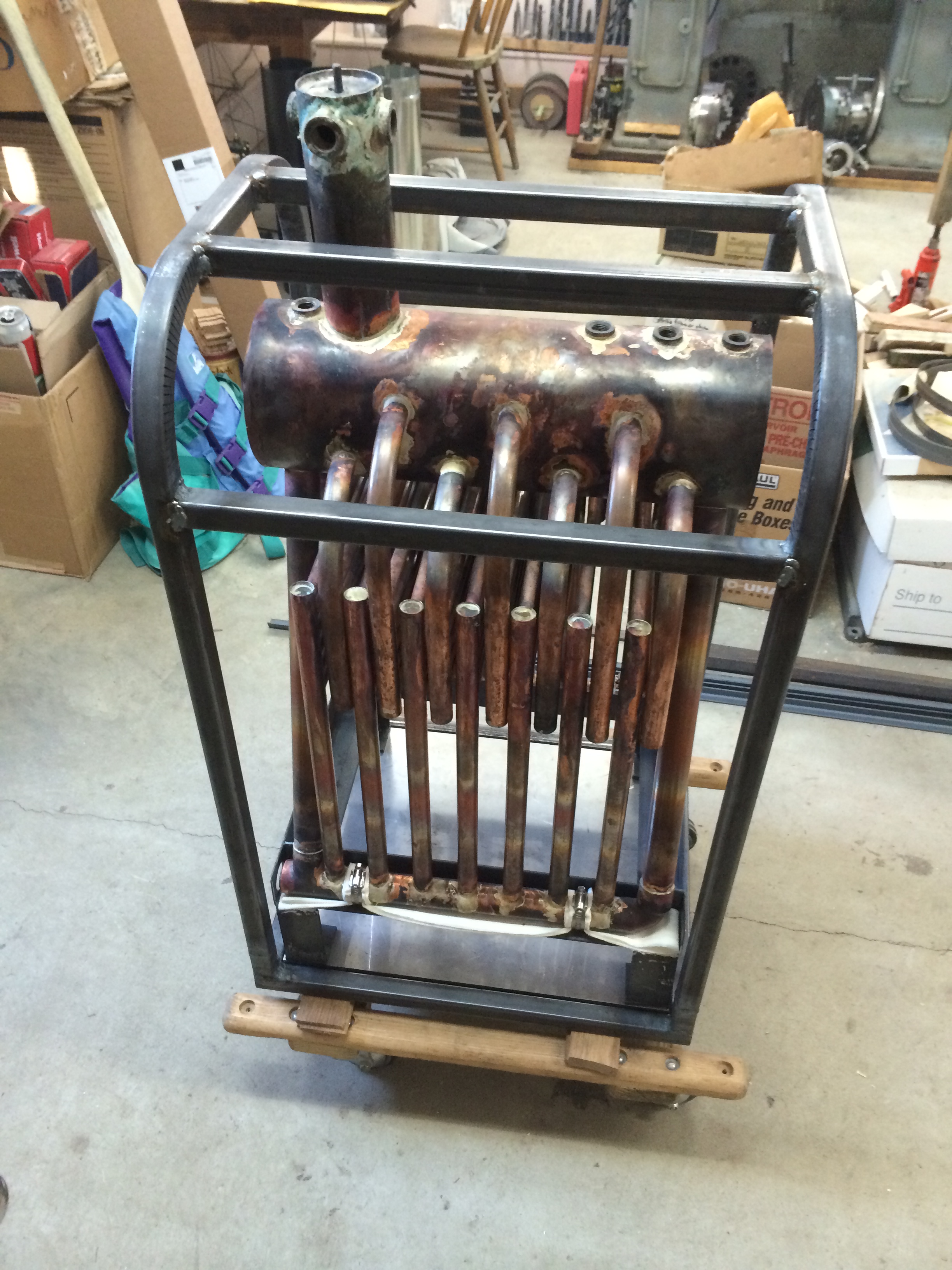
You will see from the First Fitting below how the hose clamps hold the Pressure Vessel to these slots.
Machining Pressure Vessel Hold down. (3/31/2014)
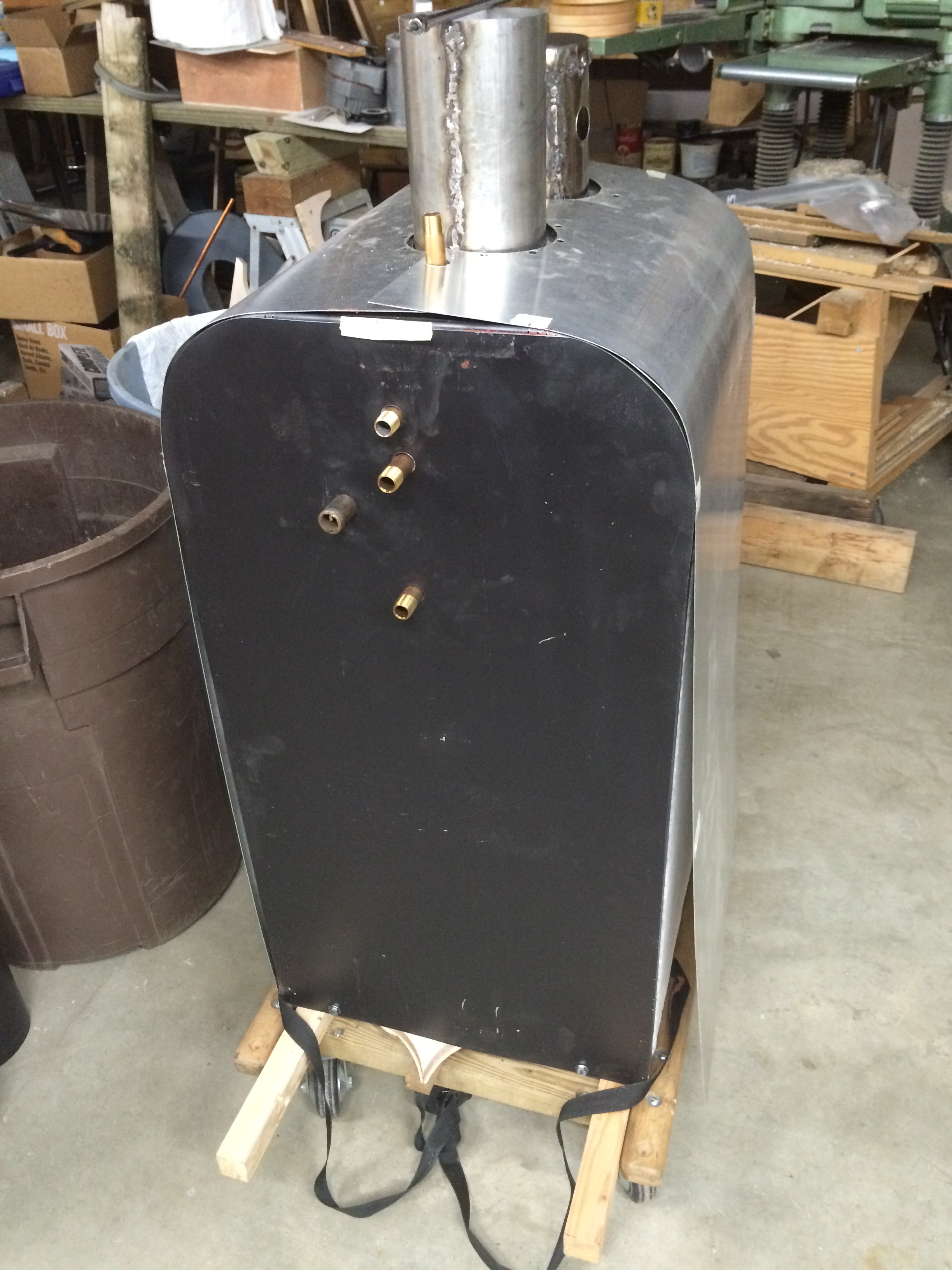
First Fitting 1. (4/2/2014)
First Fitting 2. (4/2/2014)
First Fitting 3. (4/2/2014)
#################################################
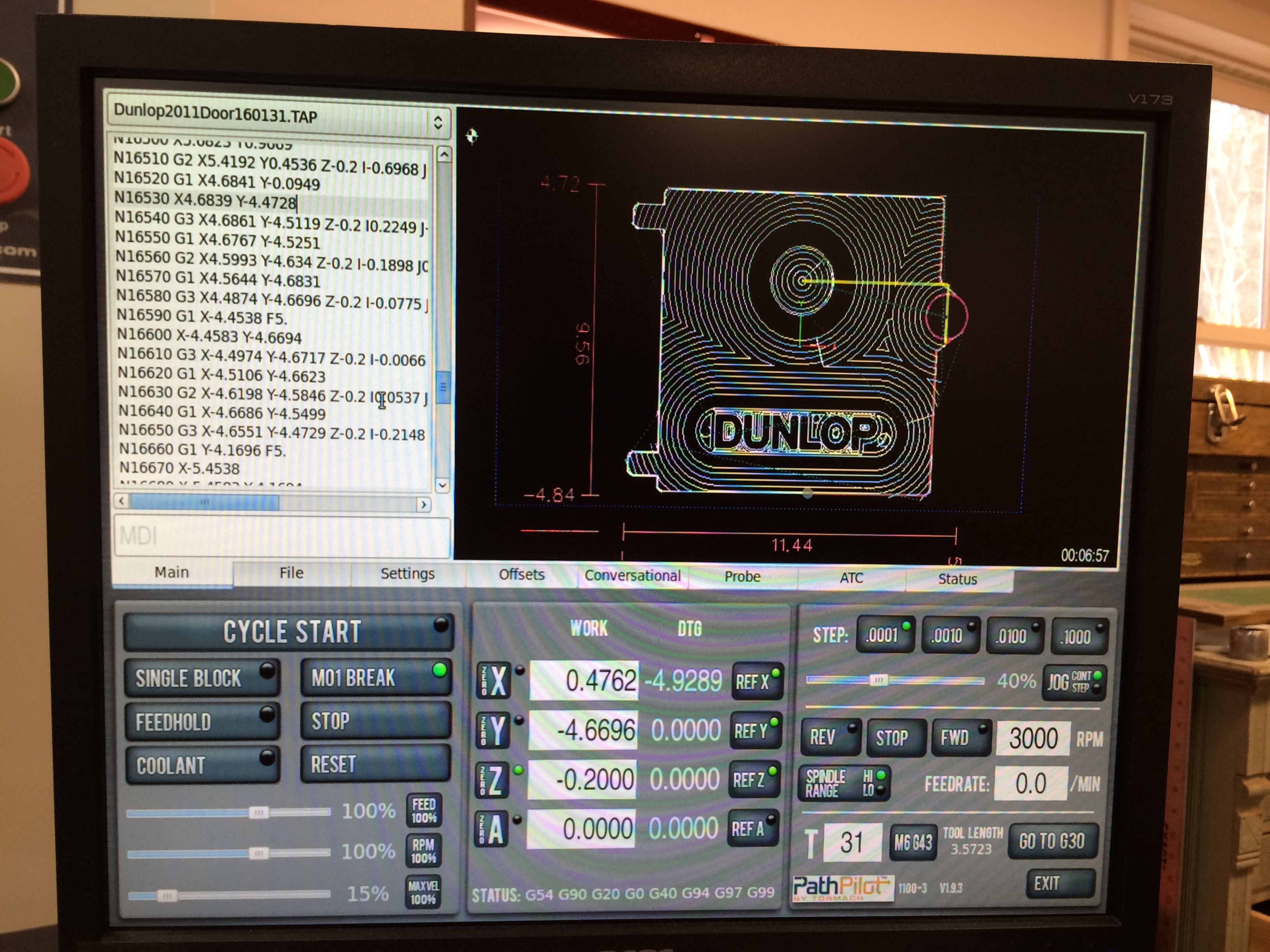
More later. ... It has been a long time since my last post on this project. I wanted a cast door, but the local iron foundry had a fire a few years ago and will not be reopened.
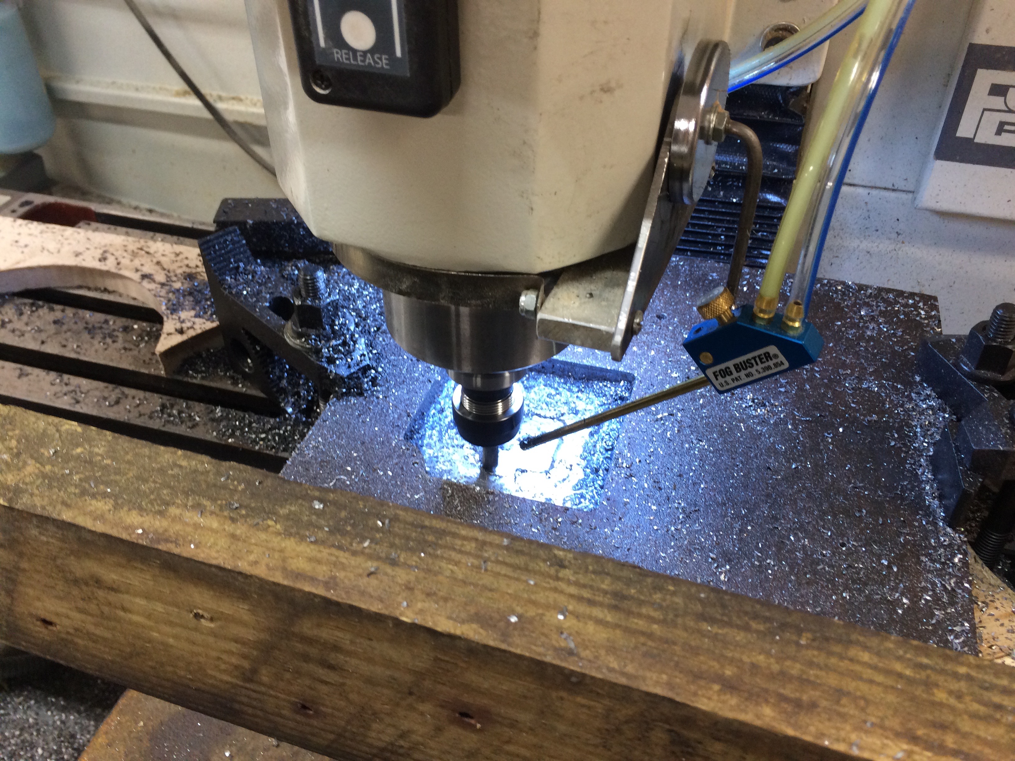
Machine console (2/27/2016)
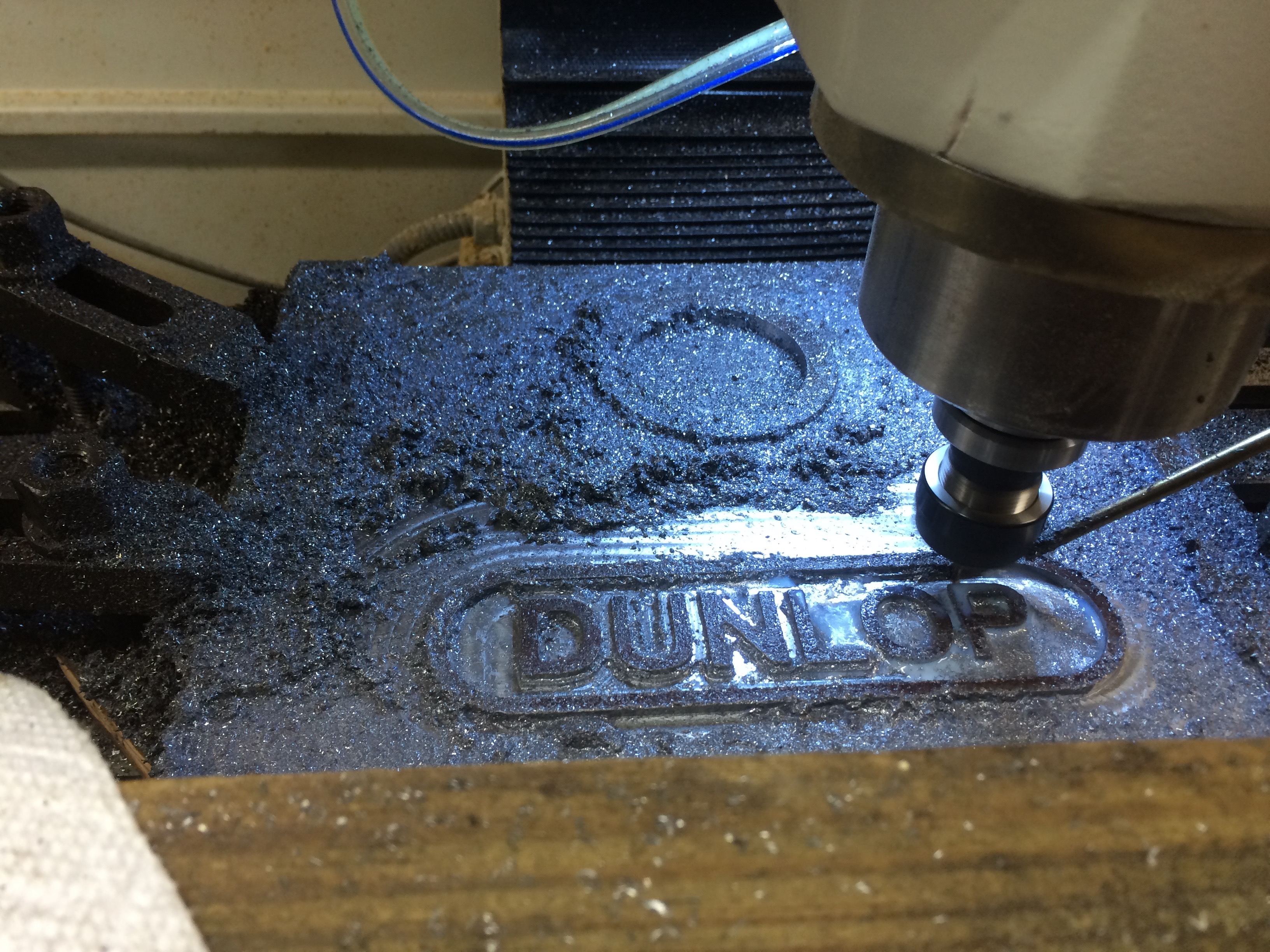
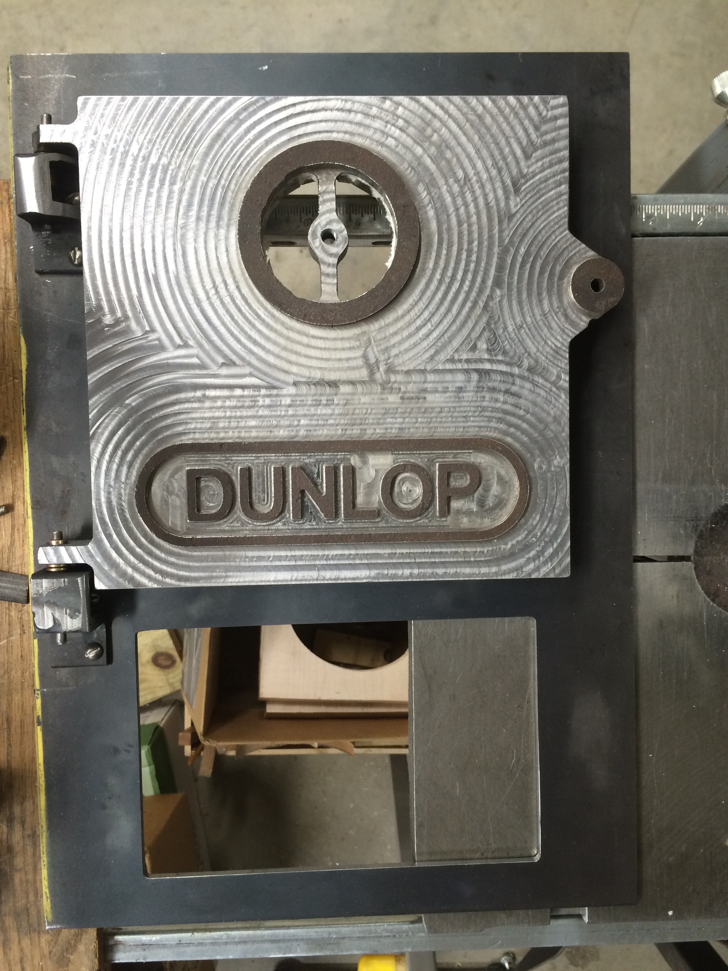
Machineing Boiler Door with Name (2/7/2016)
I used up a few End Mills clearing the front surface and hogging out the back of the 1" plate steel.
Having done the hogging out of the back, made room for insulation and lightened up the door a lot.
As you can see by the dates, I was a bit intimidated by cutting this much steel.
I made the door 5/16" thick.
I probably should have made it 1/4" thick...
I also had a few out of town trips during this time.
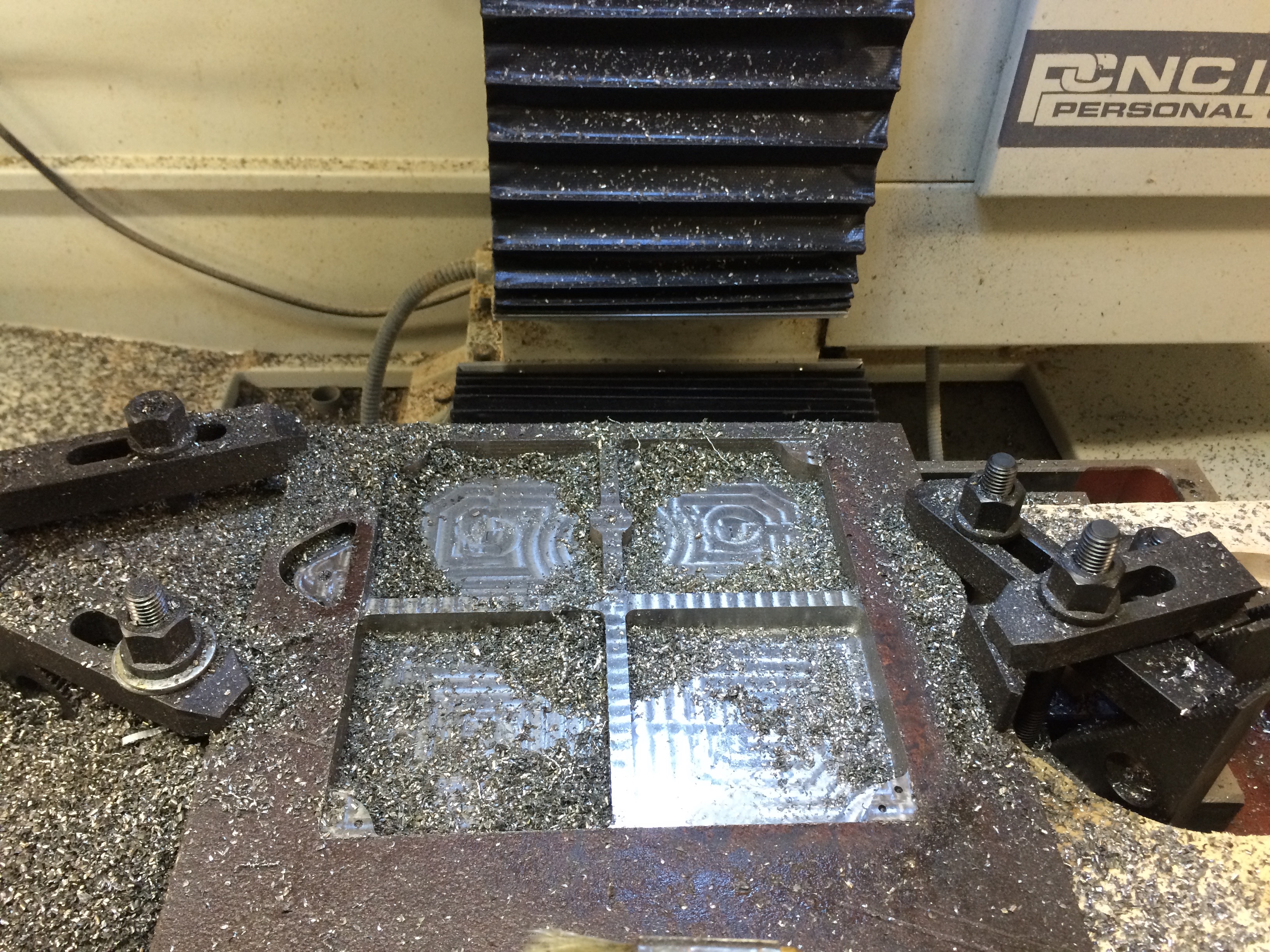
As you can see there are also a lot of chips. What you do not see is that I cleared them several times. This is a new layer is that you are seeing.
I think the expansion ratio is something like 8 to 1, chips to solid metal.
First of 4 pockets in the back of the boiler door (3/1/2016)
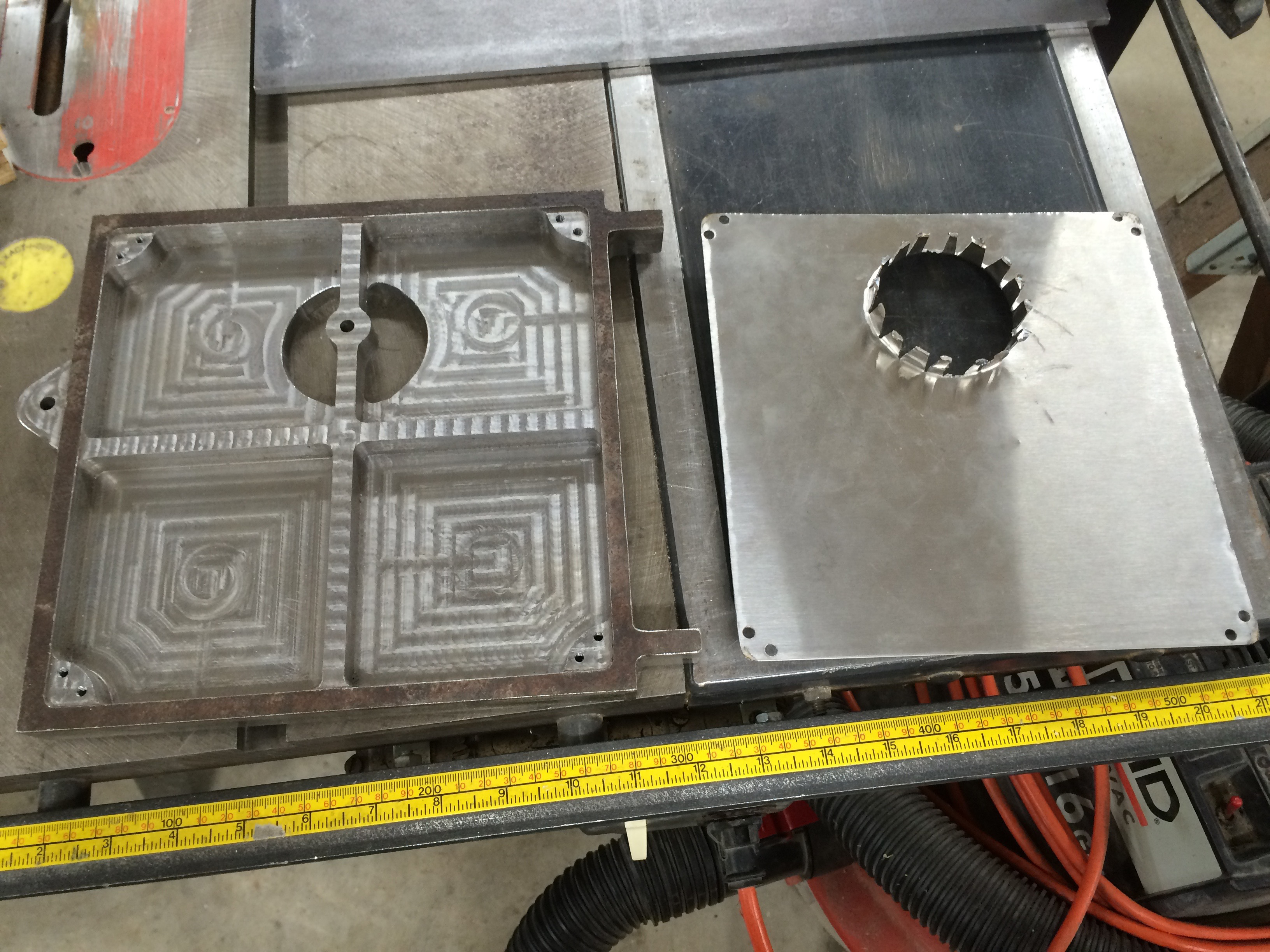
Four pockets made (3/3/2016)
Door and cover before insulation (5/30/2016)
The patterning of the End Mill looks like the surface might not be flat, but it is hard to feel anything.
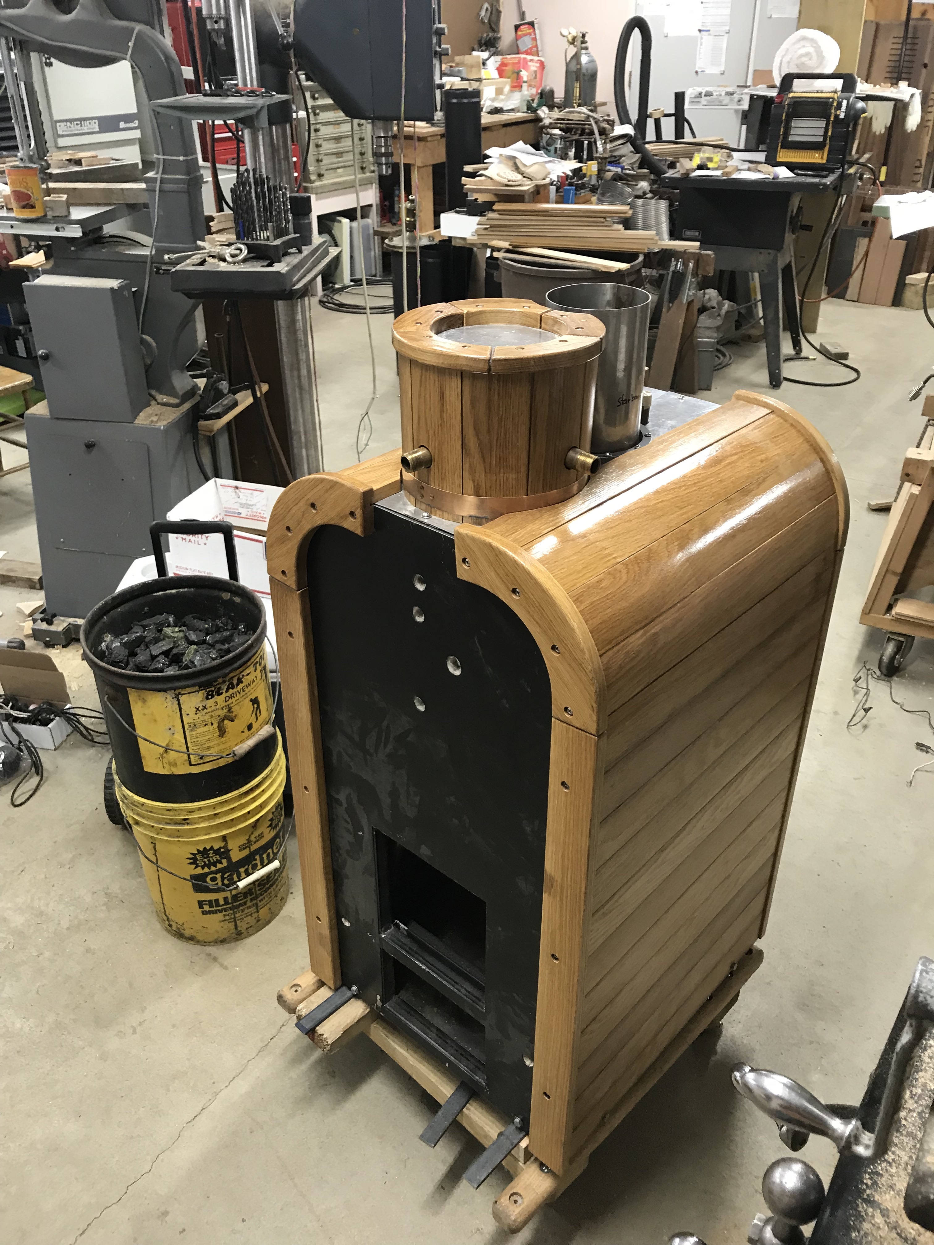
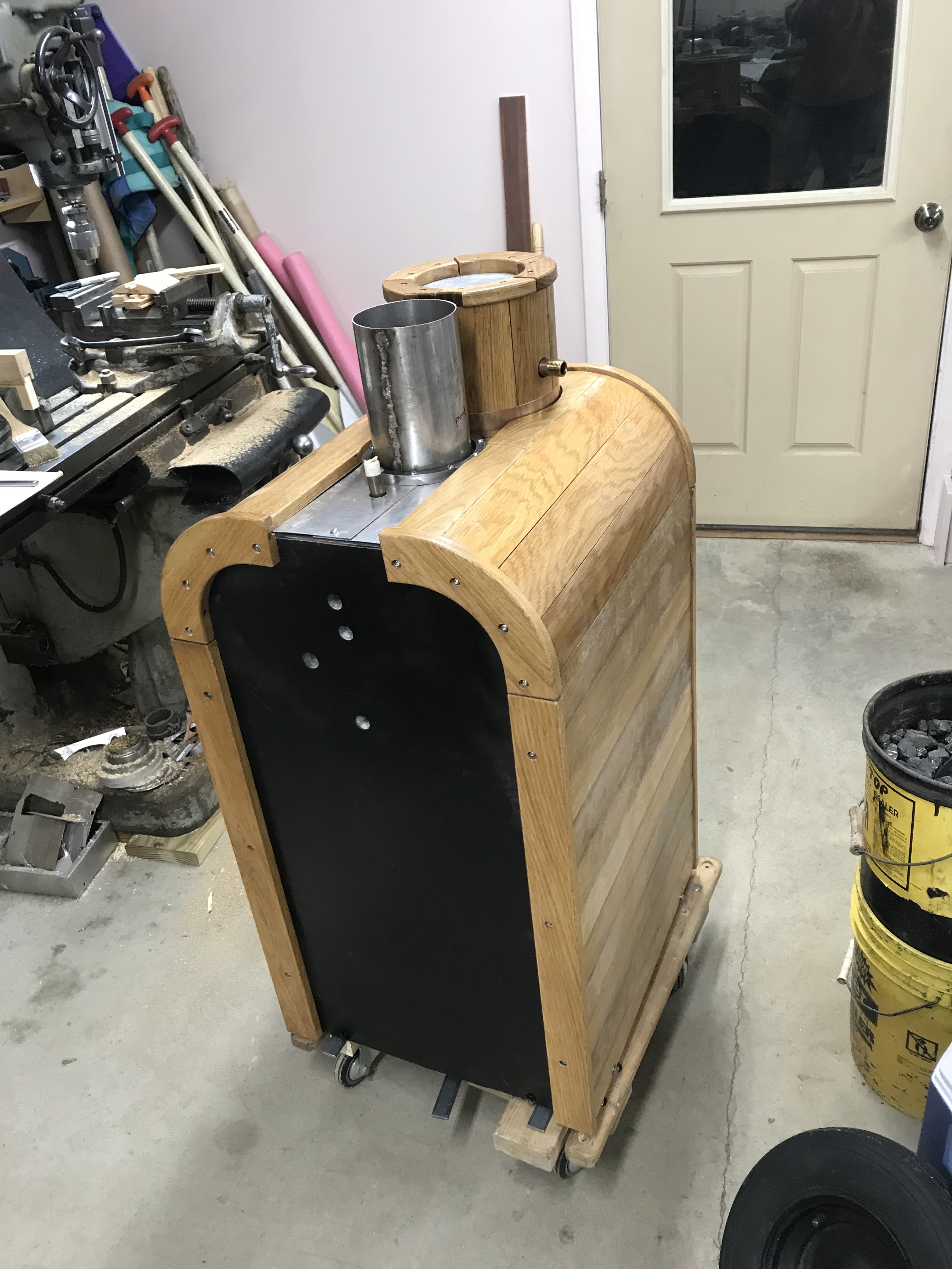
The Bow cover over 1" refractory insulation. (6/6/2016)
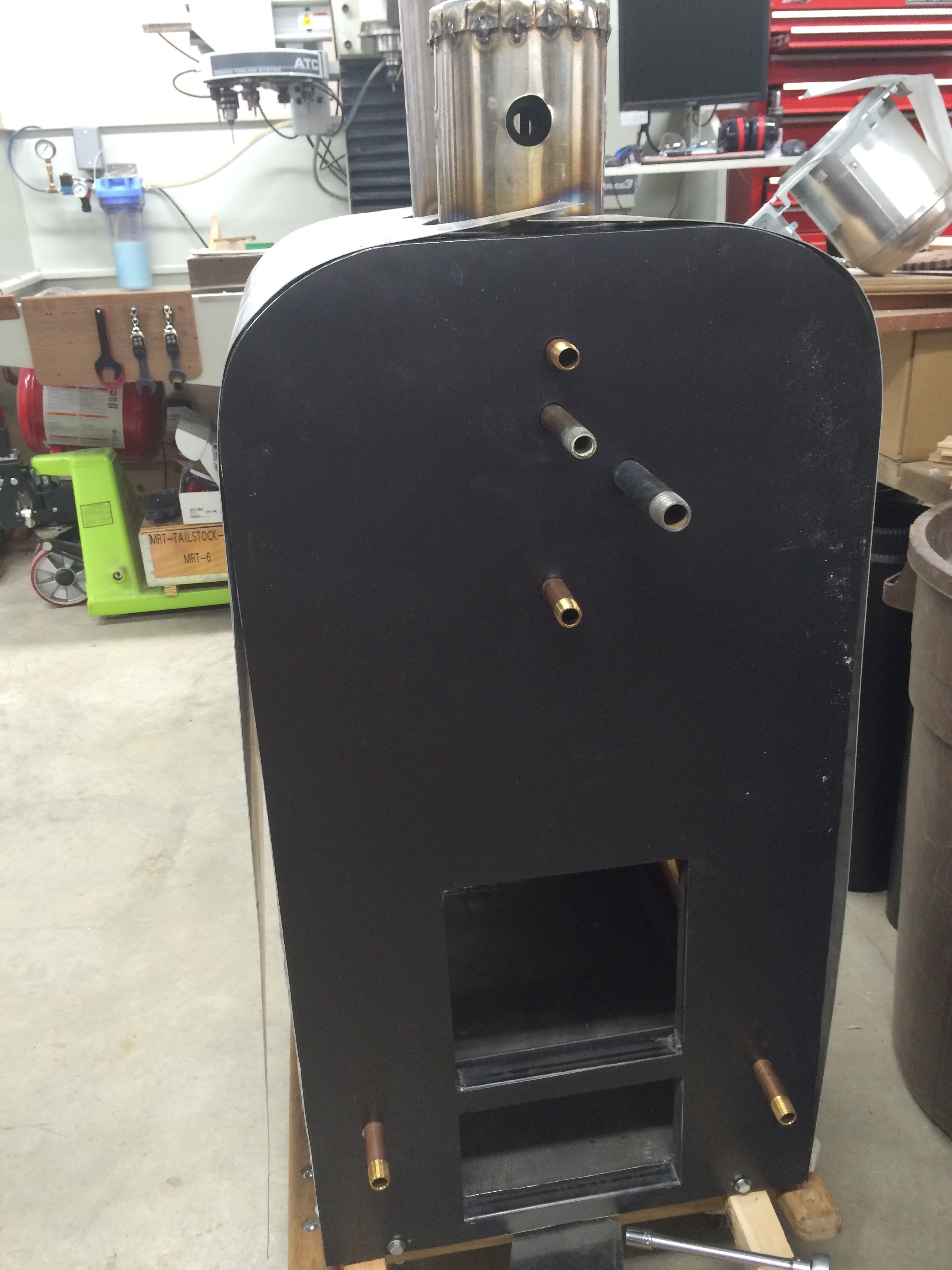
The stern has a fire door and damper/ash door. (6/6/2016)
I sealed the inner Stainless Steel jacket with fire stop caulk. I have done the same for the Aluminum outer jacket.
[I have enough air leaks in my boiler in S/L Aurora Borealis that it will run at about 1/8th speed with the damper closed.]
Fire door and door frame. (6/6/2016)
It has been a long time since I did much work on this boiler. It is now January, 2018.
I used the CNC machine to cut white oak flooring into curved pieces of wood.
This was automated but still took significant time.
It was complicated by the length of wood needed being longer than the CNC machine can cut.
The finished product is nice, but a lot of work (for the CNC machine).
I used a 3/8" Ball End Mill for cutting these curved boards.
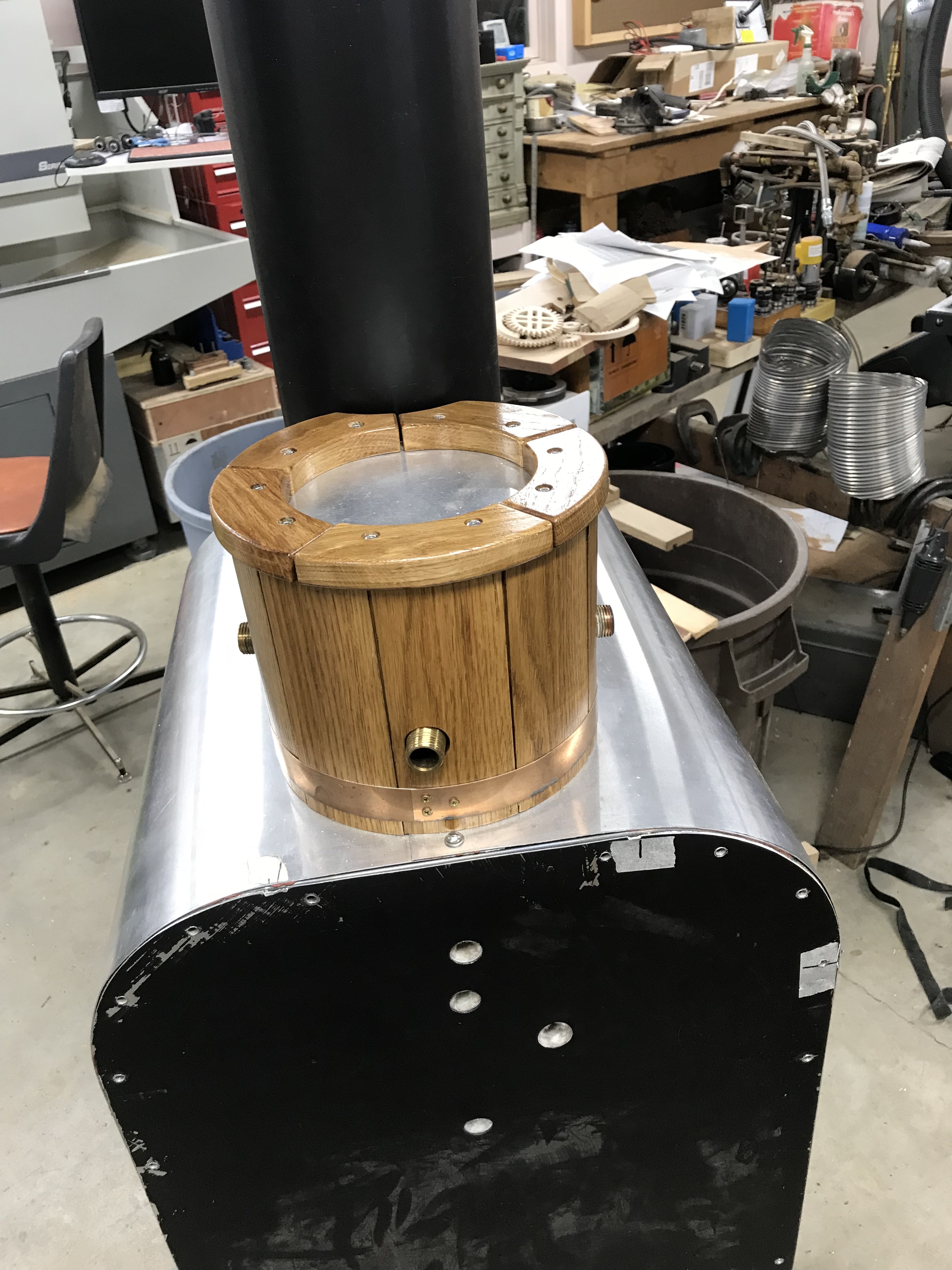
The Steam Dome has a beryllium copper band at the bottom and 5 keyed pieces of white oak on the top.
Steam Dome with Lagging. (1/9/2018)
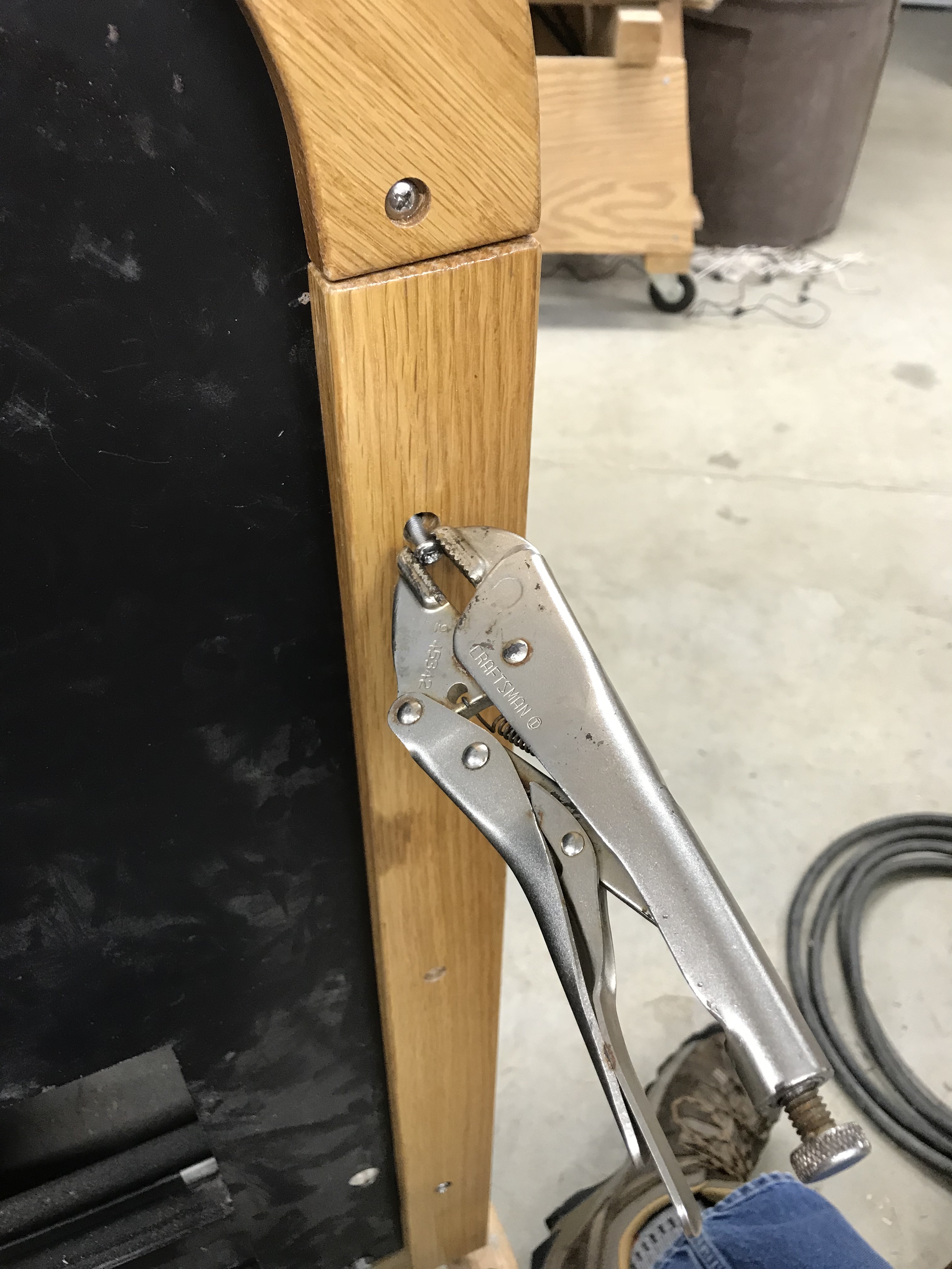
I had serious problems with jammed screws. Three out of three jammed. Eventually I decided to torque them until they broke. These screws, 10-32, were through both sides of 1" square tubing and into a SS nut welded on the second side. The second side of the square tube was also part of the threading. These holes were retapped before the insulation and aluminum (sealed with 650F silicon gasket/caulk). Luckily, the breaks of the 10-32 screws were in the second side square tube or at least flush with the threaded surface such that I could drill out the broken off screw and retap.
Jammed screw. (1/21/2018)
The final lagging looks really nice.
The horizontal white oak is keyed into slots in the vertical edge pieces.
There are four 1/4"-20 bolts in at the base (bottom) of the horizontal lagging, two per side.
These bolts hold the lagging from sliding down to the floor.
They are threaded into the first layer of square tubing making the pressure vessel mount.
[Be aware that to remove the boiler case, four bolts (2 bow, 2 stern) and four bolts (2 starboard, 2 port) and all through case plumbing must be removed.
This means that no bolts in the hot fire box need to be removed to take the boiler case off (no lagging needs to be removed).]